Digital Modules
4-16
S7-400, M7-400 Programmable Controllers Module Specifications
A5E00069467-07
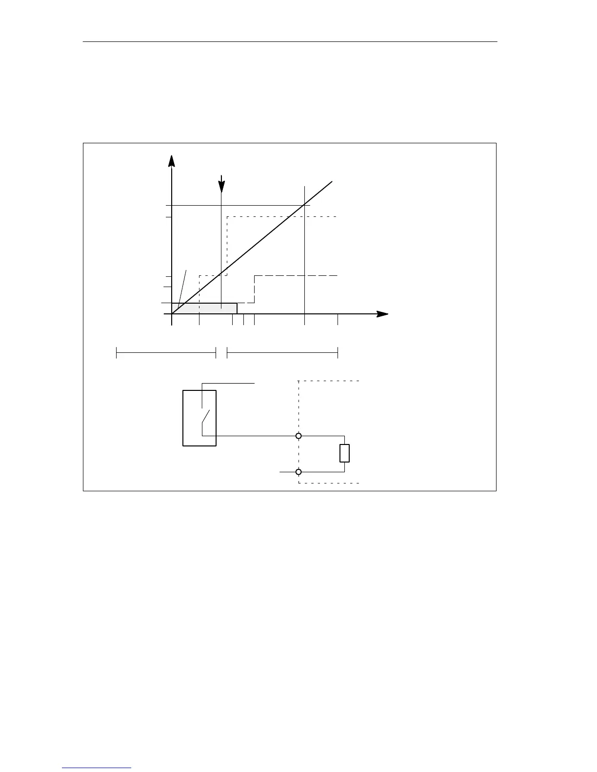
Input Characteristic Curve for Digital Inputs
As long as the current flowing into the module remains v 1.5 mA, the module
recognizes this as a “0” signal.
0.5
1.5
2
6
7
0 5 11 1315 24 30
I
min
to IEC 61131; type 2
I
min
to IEC 61131; type 1
Typ. switching threshold
(9.5 V)
Resistance characteristic
curve
L+ (V)
– 30 V
I
E
(mA)
“0” “1”
1
0
L+
M
I v 1.5 mA --> “0” signal
PLC
input resistance
2-Wire BERO
BERO
standard
I v 1.5 mA
Figure 4-1 Input Characteristic Curve for Digital Inputs
IEC 61131, Type 1 in the Case of the Digital Input Module (6ES7421-1BL01-0AA0)
The input current in the case of the digital input module (6ES7421-1BL01-0AA0)
reaches 1.5 mA only above the +5 V switching threshold but under the switching
threshold of the module (typ. 9.5 V). Therefore only type 1 can be specified with the
IEC 61131 standard.