Interface Submodules
13-35
S7-400, M7-400 Programmable Controllers Module Specifications
A5E00069467-07
Meaning of Signals
The following table shows the meanings of the signals in Figure 13-10.
Table 13-38 Meaning of the Signals of the X1 Socket of the IF 961-AIO Interface
Submodule
Signal
Meaning
MV
0+
... MV
3+
Analog inputs: Voltage
MI
0+
... MI
3+
Analog inputs: Current
M
0-
... M
3-
Reference potential of the analog inputs
QV
0
, QV
1
Analog outputs: Voltage
QI
0
, QI
1
Analog outputs: Current
S
0
, S
1
Reference potential of the analog outputs
L
+
Voltage supply input 24 VDC
L1
+
, L2
+
Outputs for supplying the 2-wire transducers (24 VDC)
M Ground (0 V)
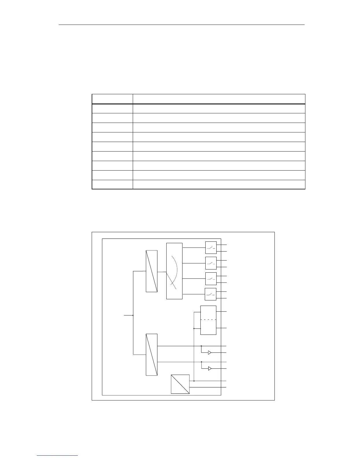
Circuit Block Diagram
Figure 13-11 shows the circuit block diagram of the IF 961-AIO interface
submodule.
M
L+
A
D
Internal
supply
U
I
U
I
U
I
U
I
CH 0
CH 1
CH 2
CH 3
A
D
U
I
U
I
CH 0
CH 1
Inputs
Outputs
Internal
data bus
L1
+
L2
+
Current
limiter
Figure 13-11 Circuit Block Diagram of the IF 961-AIO Interface Submodule