Interface Submodules
13-36
S7-400, M7-400 Programmable Controllers Module Specifications
A5E00069467-07
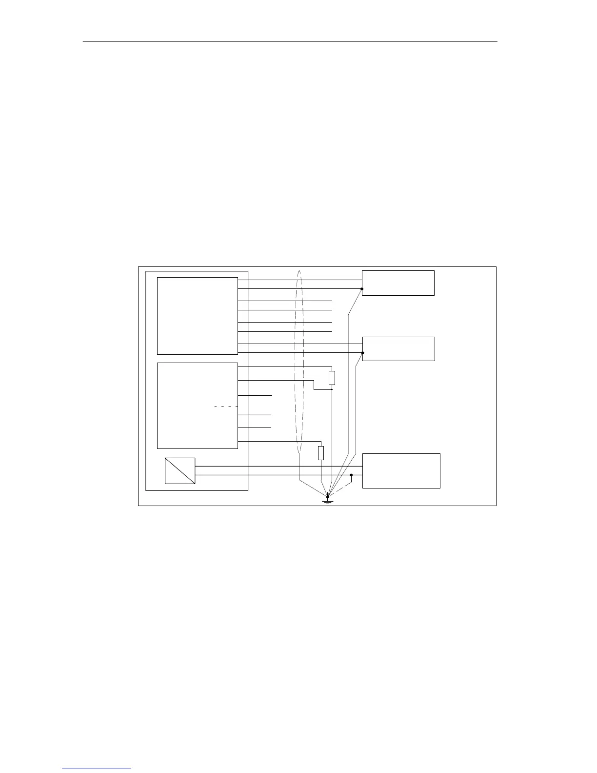
Grounding for the Analog Inputs
If the valid Common Mode area (V
CM
) cannot be retained, the analog inputs must
be grounded. To do this, the ground lines of the individual analog inputs (1) and the
shielding must be routed to the grounding point isolated.
Refer to Figure 13-12 for the grounding of the analog inputs.
Grounding for the Analog Outputs
To do this, the ground lines of the individual analog outputs (2) and the shielding
must be routed to the grounding point isolated.
With a grounded installation of the load current supply, the ground terminal of the
load current supply must be connected with its own line to the grounding point (3).
The following figure shows the grounding of the analog outputs.
M
L+
(3)
R
L
Analog
input
Ground point
Load current
supply
M
L+
Analog
output
R
L
CH 0
CH 1
IF 961-AIO
QI
0
QI
1
S
0
QV
0
QV
1
S
1
Transducer
-
+
Transducer
-
+
:
:
- 1
(2)
Figure 13-12 Grounding the Analog Inputs/Outputs of the Interface Submodule IF 961-AIO