Interface Submodules
13-34
S7-400, M7-400 Programmable Controllers Module Specifications
A5E00069467-07
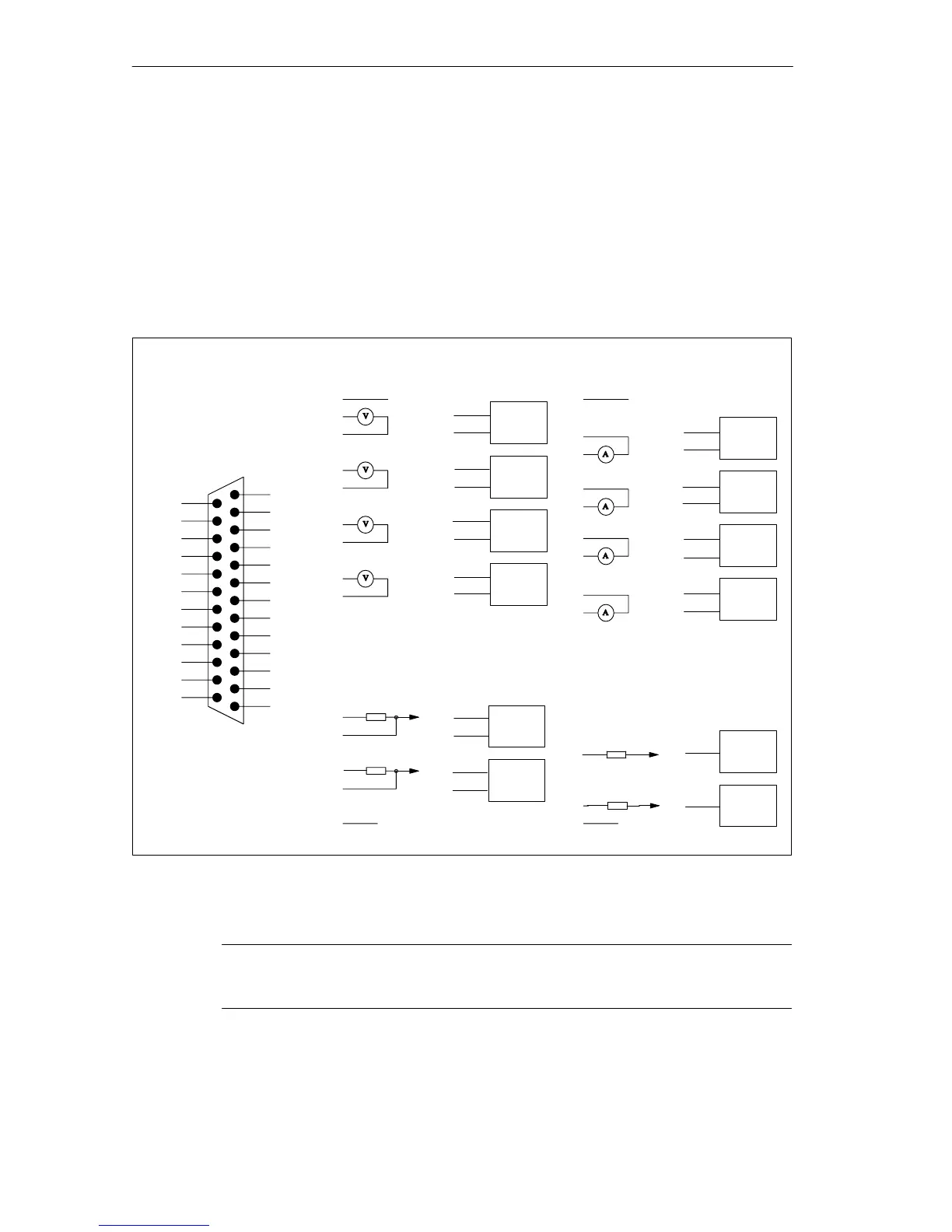
13.7.1 Pin Assignments and Terminal Connection Diagram
X1 Socket
There is a 25-pin sub D socket connector on the frontside of the submodule for
plugging in the connecting cable.
Figure 13-10 shows the assignments for the X1 socket and the terminal
connection diagram of the submodule.
V
Pinout diagram voltage measurement
M
0-
MI
1+
MV
2+
M
2-
M
3-
MI
3+
QI
1
CH 0
CH 1
CH2
CH 3
CH 0
CH1
M
M
1-
Pinout diagram voltage output
MV
1+
M
1-
CH 1
MV
3+
M
3-
CH 3
MI
0+
CH 0
M
0-
M
2-
MI
2+
CH 2
QV
1
S
1
CH1
QV
0
S
0
QI
0
CH 0
R
L
L +
R
L
V
Pinout diagram current
measurement
2
4
6
8
10
11
13
15
16
17
18
19
20
21
22
23
24
12
9
M
Pinout diagram current output
R
L
1L +
A
Ground bar
of the PLC
R
L
A
Ground bar
of the PLC
2
4
6
8
10
11
13
15
16
17
18
19
20
21
22
23
24
12
9
1
MV
0+
13 M
12 S
1
11 QV
1
10 QV
0
9S
0
8MV
3+
7NC
6MV
2+
5NC
4MV
1+
3NC
2MV
0+
1L+
L2+ 25
QI
1
24
QI
0
23
M
3-
22
MI
3+
21
M
2-
20
MI
2+
19
M
1-
18
MI
1+
17
M
0-
16
MI
0+
15
L1+ 14
Figure 13-10 X1 Socket Assignments (25-Pin Sub D Connector) and Terminal Connection Diagram of the
IF 961-AIO
Note
Use only shielded cables for connecting the inputs and outputs.

 Loading...


