Parameter Sets for Signal Modules
A-7
S7-400, M7-400 Programmable Controllers Module Specifications
A5E00069467-07
A.3 Parameters of the Digital Output Modules
Parameters
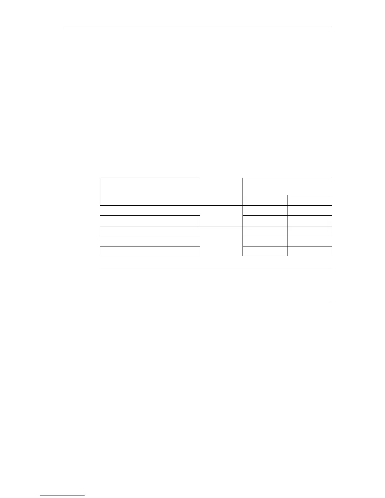
The table below contains all the parameters you can set for digital output modules.
The comparison shows:
• Which parameters you can change with STEP 7 and
• Which parameters you can change with SFC 55 “WR_PARM”
The parameters set with STEP 7 can also be transferred to the module with SFCs
56 and 57 (refer to the STEP 7 manuals).
Table A-3 Parameters of the Digital Output Modules
Parameter
Data Record
No.
Parameters Can Be Assigned
with ...
... SFC 55 ... STEP 7
Destination CPU for Interrupts
No Yes
Diagnostics
0
No Yes
Diagnostic interrupt enable Yes Yes
Reaction to CPU STOP
1
Yes Yes
Enable substitute value “1” Yes Yes
Note
If you want to enable the diagnostic interrupt in the user program in data record 1,
you must enable the diagnosis in data record 0 beforehand using STEP 7.