Parameter Sets for Signal Modules
A-8
S7-400, M7-400 Programmable Controllers Module Specifications
A5E00069467-07
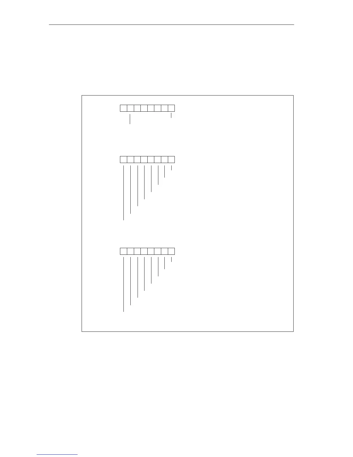
Structure of Data Record 1
The figure below shows the structure of data record 1 (bytes 0, 1 and 2) for the
parameters of the digital output modules.
You enable a parameter by setting the corresponding bit to “1”.
Byte 0
76 0
Diagnostic interrupt enable
Reaction to CPU STOP
Byte 1
76 0
54321
Byte 2
76 0
Enable substitute value 1 on channel 15
54321
Substitute value
Substitute value
Enable substitute value 1 on channel 7
Enable substitute value 1 on channel 6
Enable substitute value 1 on channel 5
Enable substitute value 1 on channel 4
Enable substitute value 1 on channel 3
Enable substitute value 1 on channel 2
Enable substitute value 1 on channel 1
Enable substitute value 1 on channel 0
Enable substitute value 1 on channel 8
Enable substitute value 1 on channel 9
Enable substitute value 1 on channel 10
Enable substitute value 1 on channel 11
Enable substitute value 1 on channel 12
Enable substitute value 1 on channel 13
Enable substitute value 1 on channel 14
Figure A-3 Data Record 1 for Parameters of the Digital Output Modules