Parameter Sets for Signal Modules
A-9
S7-400, M7-400 Programmable Controllers Module Specifications
A5E00069467-07
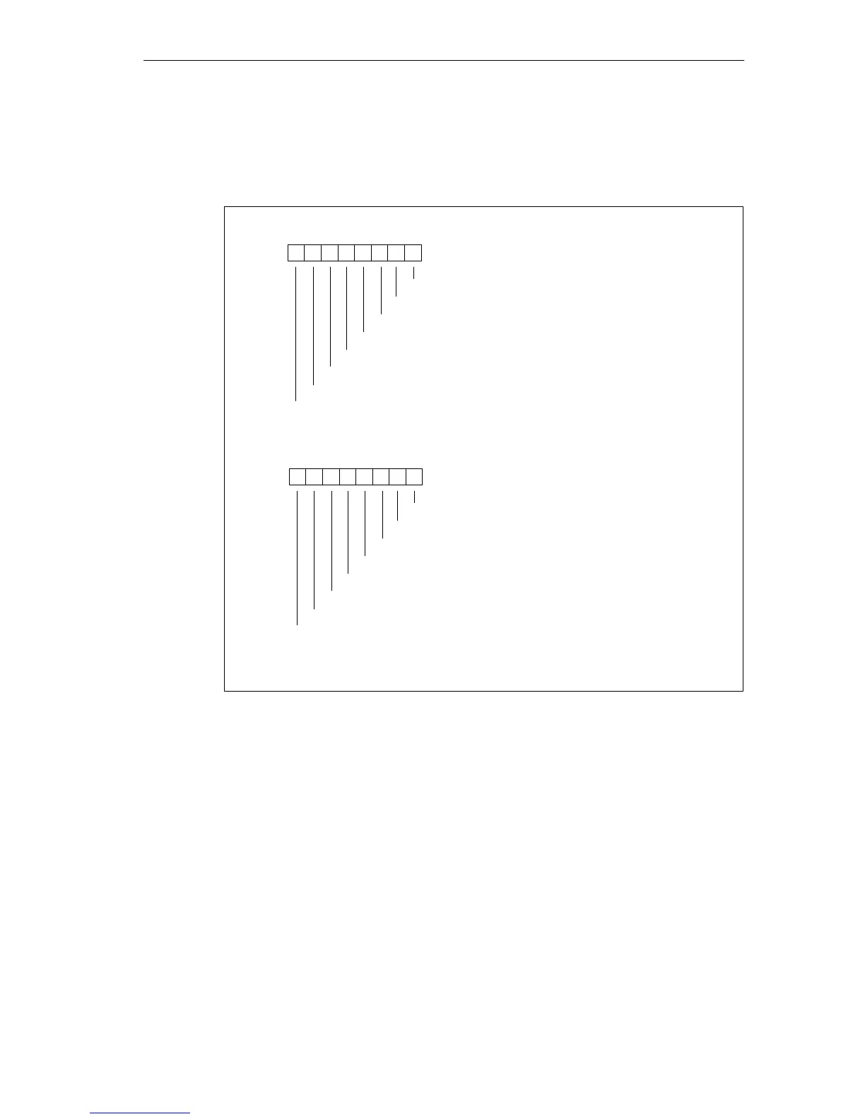
The figure below shows the structure of data record 1 (bytes 3 and 4) for the
parameters of the digital output modules.
You enable a parameter by setting the corresponding bit to “1”.
Byte 3*
76 0
54321
Byte 4*
76 0
Enable substitute value 1 on channel 31
54321
Substitute value
Substitute value
Enable substitute value 1 on channel 23
Enable substitute value 1 on channel 22
Enable substitute value 1 on channel 21
Enable substitute value 1 on channel 20
Enable substitute value 1 on channel 19
Enable substitute value 1 on channel 18
Enable substitute value 1 on channel 17
Enable substitute value 1 on channel 16
Enable substitute value 1 on channel 24
Enable substitute value 1 on channel 25
Enable substitute value 1 on channel 26
Enable substitute value 1 on channel 27
Enable substitute value 1 on channel 28
Enable substitute value 1 on channel 29
Enable substitute value 1 on channel 30
* Bytes 3 and 4 are not relevant for SM 421; DO 16 20-125 VDC/1.5 A
Figure A-4 Data Record 1 for Parameters of the Digital Output Modules