Parameter Sets for Signal Modules
A-10
S7-400, M7-400 Programmable Controllers Module Specifications
A5E00069467-07
A.4 Parameters of the Analog Input Modules
Parameters
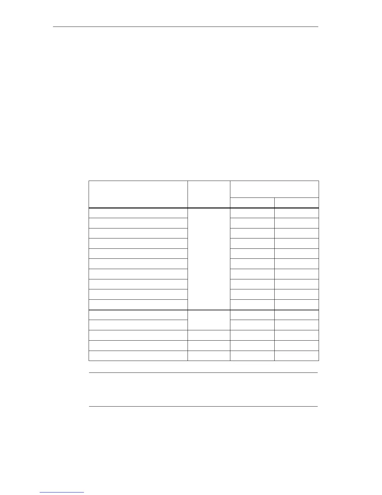
The table below contains all the parameters you can set for analog input modules.
You will see which parameters you can modify from the list:
• in STEP 7
• with SFC 55 ”WR_PARM”
The parameters set with STEP 7 can also be transferred to the module with SFCs
56 and 57 (refer to the STEP 7 manuals).
Table A-4 Parameters of the Analog Input Modules
Parameter
Data Record
No.
Parameters Can Be Assigned
with ...
... SFC 55 ... STEP 7
Destination CPU for Interrupts No Yes
Measuring Type No Yes
Measuring Range No Yes
Diagnostics No Yes
Temperature Unit
No Yes
Temperature Coefficient
0
No Yes
Interference Suppression No Yes
Smoothing No Yes
Reference Junction No Yes
End-of-scan-cycle interrupt No Yes
Diagnostic interrupt enable
Yes Yes
Hardware interrupt enable
1
Yes Yes
Reference Temperature 1 Yes Yes
High Limit 1 Yes Yes
Low Limit 1 Yes Yes
Note
If you want to enable the diagnostic interrupt in the user program in data record 1,
you must enable the diagnosis in data record 0 beforehand using STEP 7.

 Loading...


