Digital Modules
4-24
S7-400, M7-400 Programmable Controllers Module Specifications
A5E00069467-07
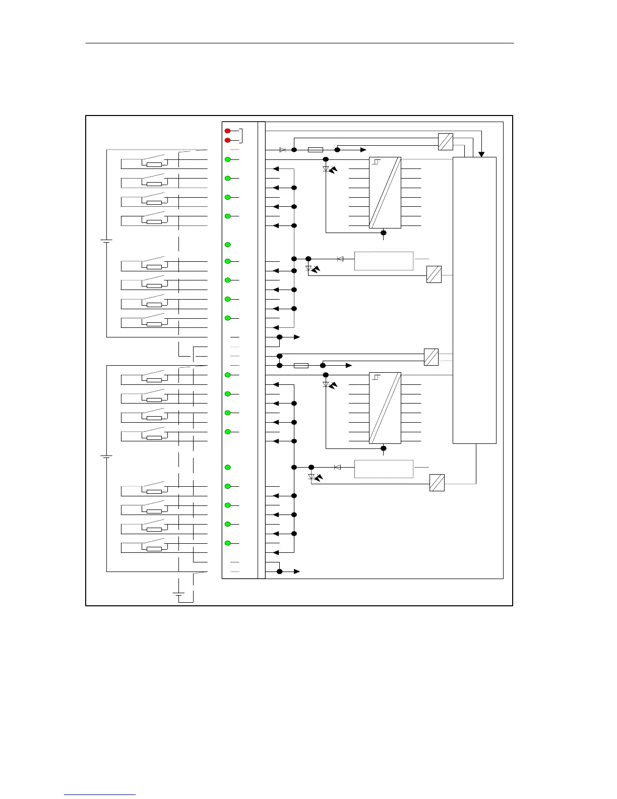
Terminal Assignment and Block Diagram of the SM 421; DI 16 24 VDC
INT
F
EXTF
1L+
0
1
2
3
1Vs
4
5
6
7
1M
1M
2L+
2L+
0
1
2
3
2Vs
4
5
6
7
2M
2M
1L+
2M
2L+
1M
ML+
1L+
1L+
2L+
1M
2M
2M
1M
Backplane bus interface
24 V
24 V
24 V
Front connector monitoring
Monitoring of external auxiliary supply 1L+
Monitoring of internal voltage
Monitoring of sensor supply 1Vs
2L+
Monitoring of external auxiliary supply 2L+
Monitoring of internal voltage
Monitoring of sensor supply 2Vs
1
2
3
4
5
6
7
8
9
10
11
12
13
14
15
16
17
18
19
20
21
22
23
24
25
26
27
28
29
30
31
32
33
34
35
36
37
38
39
40
41
42
43
44
45
46
47
48
Short-circuit
protection
Short-circuit
protection
Figure 4-4 Terminal Assignment and Block Diagram of the SM 421; DI 16 24 VDC