Power Supply Modules
3-28
S7-400, M7-400 Programmable Controllers Module Specifications
A5E00069467-07
3.10 Power Supply Module PS 407 20A;
(6ES7407-0RA01-0AA0)
Function
The PS 407 20 A power supply module is designed for connecting to either an AC
line voltage of 85 to 264 VAC or a DC line voltage of 88 to 300 VDC and
supplies 5 VDC/20 A and 24 VDC/1 A on the secondary side.
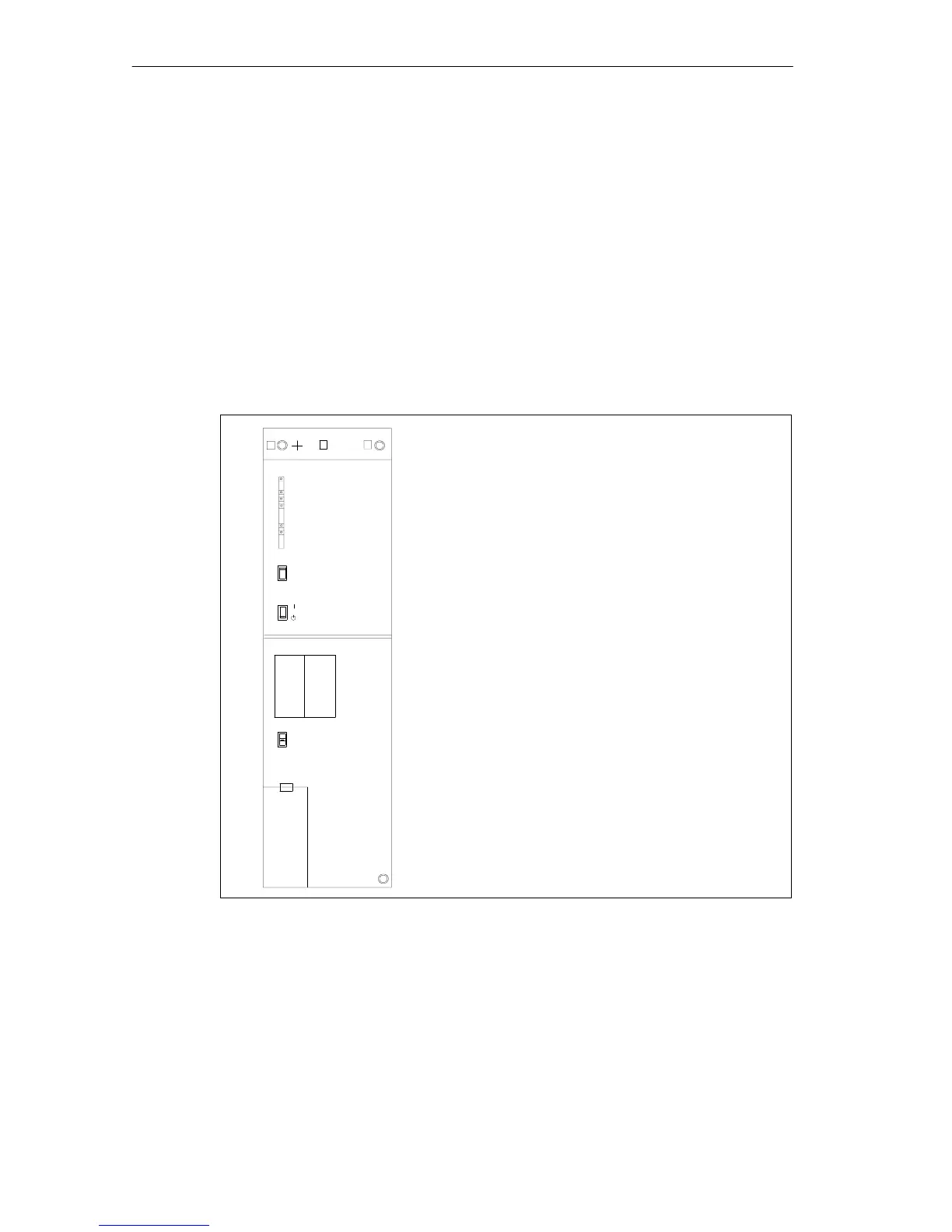
Controls and Indicators of the PS 407 20 A
• FMR pushbutton (Failure Message Reset)
• Standby switch (does not cut off mains)
• Switches BATT. INDIC.
2 BATT, OFF, 1 BATT
• Battery compartment
• 3-pin plug-in power connector
• Fixing screw
• Fixing screws
• LEDs INTF,
BAF, BATT1F, BATT2F, 5 VDC, 24 VDC
PS 407 20A
407-0RA01-0AA0
X2
34
1
FMR
BATT. INDIC.
2 BATT
1 BATT
OFF
INTF
BAF
BATTF
5 VDC
24 VDC
BATTF
2
3
BATT.1 BATT.2
+
–
+
–
Under cover
Figure 3-6 Controls and Indicators of the PS 407 20 A
Power Connection
In contrast to the instructions on installing a power supply module in the “S7-400,
M7-400 Programmable Controllers, Hardware and Installation” manual, an AC
power connector is used for connecting the PS 407 20A to both an AC and DC
supply.