Interface Submodules
13-25
S7-400, M7-400 Programmable Controllers Module Specifications
A5E00069467-07
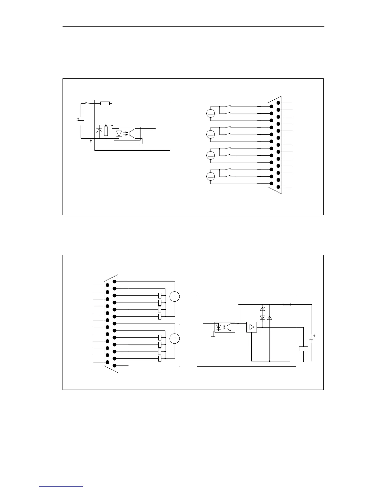
Figures 13-7 and 13-8 show the circuit block diagrams and the terminal connection
diagrams for wiring the digital inputs and digital outputs.
Terminal connection diagram
Circuit block
diagram
Internal
data bus
M
internal
13 5M
12 5L+
11 DO0
10 DO1
9 DO2
8 DO3
76M
6 6L+
5 DO4
4 DO5
3 DO6
2 DO7
1NC
DI7 25
DI6 24
4M 23
DI5 22
DI4 21
3M 20
DI3 19
DI2 18
2M 17
DI1 16
DI0 15
1M 14
Figure 13-7 Circuit Block Diagram and Terminal Connection Diagram for Wiring the Digital Inputs
Terminal connection diagram
Circuit block diagram
L+
M
M
internal
Internal
data bus
13 5M
12 5L+
11 DO0
10 DO1
9 DO2
8 DO3
76M
6 6L+
5 DO4
4 DO5
3 DO6
2 DO7
1NC
DI7 25
DI6 24
4M 23
DI5 22
DI4 21
3M 20
DI3 19
DI2 18
2M 17
DI1 16
DI0 15
1M 14
Figure 13-8 Circuit Block Diagram and Terminal Connection Diagram for Wiring the Digital Outputs

 Loading...


