EasyManuals Logo

Siemens Simatic M7-400 User Manual

Siemens Simatic M7-400
638 pages
To Next Page IconTo Next Page
To Previous Page IconTo Previous Page
Page #520 background imageLoading...
Page #520 background image
Interface Submodules
13-24
S7-400, M7-400 Programmable Controllers Module Specifications
A5E00069467-07
13.6.1 Pin Assignments
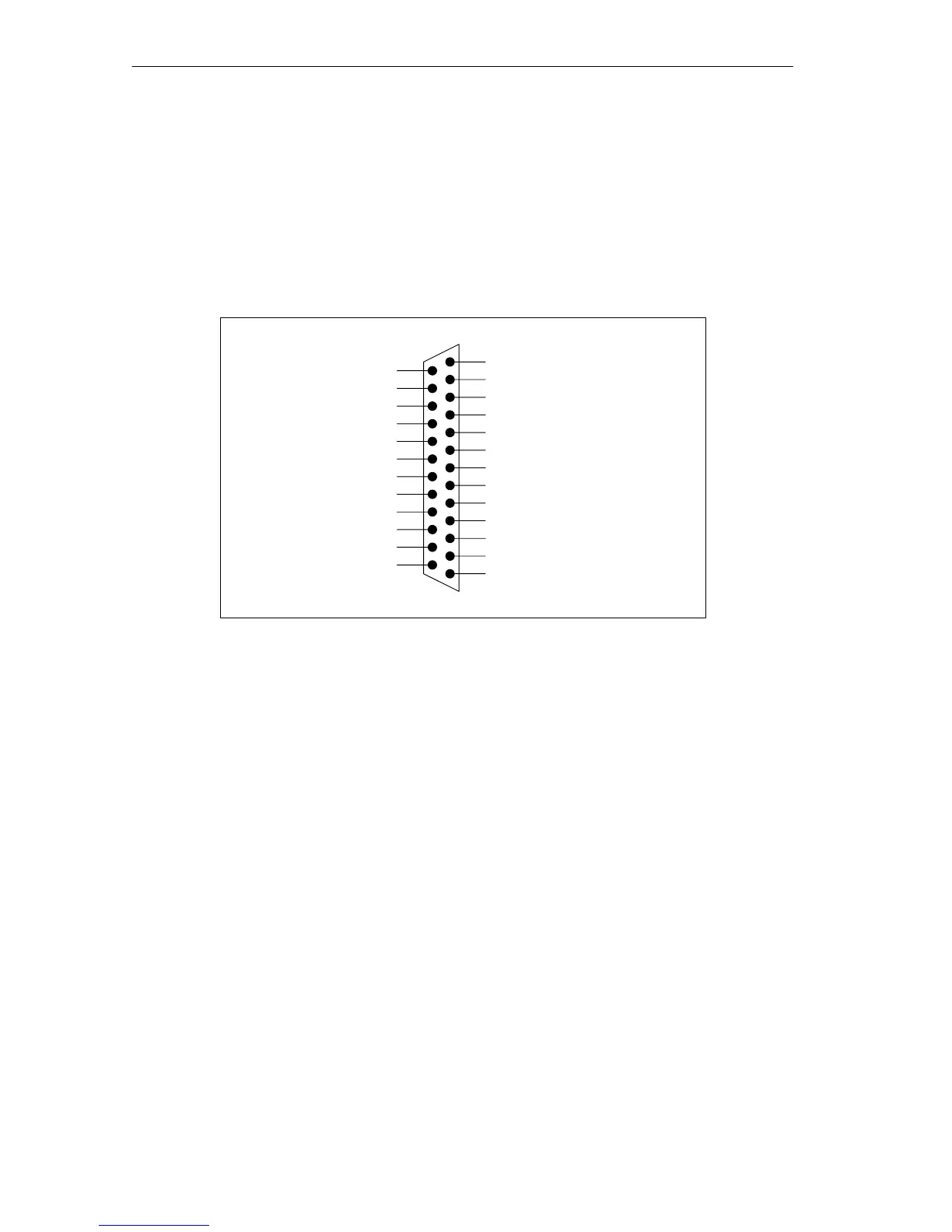
X1 Socket
There is a 25-pin sub D socket connector on the frontside of the submodule for
plugging in the connecting cable.
Figure 13-6 shows the pin assignments of the submodule.
13 5M
12 5L+
11 DO0
10 DO1
9 DO2
8 DO3
76M
6 6L+
5 DO4
4 DO5
3 DO6
2 DO7
1NC
DI7 25
DI6 24
4M 23
DI5 22
DI4 21
3M 20
DI3 19
DI2 18
2M 17
DI1 16
DI0 15
1M 14
Figure 13-6 X1 Socket Assignments, IF 961-DIO (25-Pin Sub D Connector)

Table of Contents

Questions and Answers:

Question and Answer IconNeed help?

Do you have a question about the Siemens Simatic M7-400 and is the answer not in the manual?

Siemens Simatic M7-400 Specifications

General IconGeneral
BrandSiemens
ModelSimatic M7-400
CategoryComputer Hardware
LanguageEnglish

Related product manuals