EasyManuals Logo

Siemens Simatic M7-400 User Manual

Siemens Simatic M7-400
638 pages
To Next Page IconTo Next Page
To Previous Page IconTo Previous Page
Page #393 background imageLoading...
Page #393 background image
IM 463-2
7-9
S7-400, M7-400 Programmable Controllers Module Specifications
A5E00069467-07
Setting the Address Area
The address area of the S5 I/O modules is set on the IM 314. This setting applies
only for the digital and analog I/O modules.
The address areas P, Q, IM3, and IM4 are available. Set the switch to the relevant
position to address the digital and analog I/O modules in these areas.
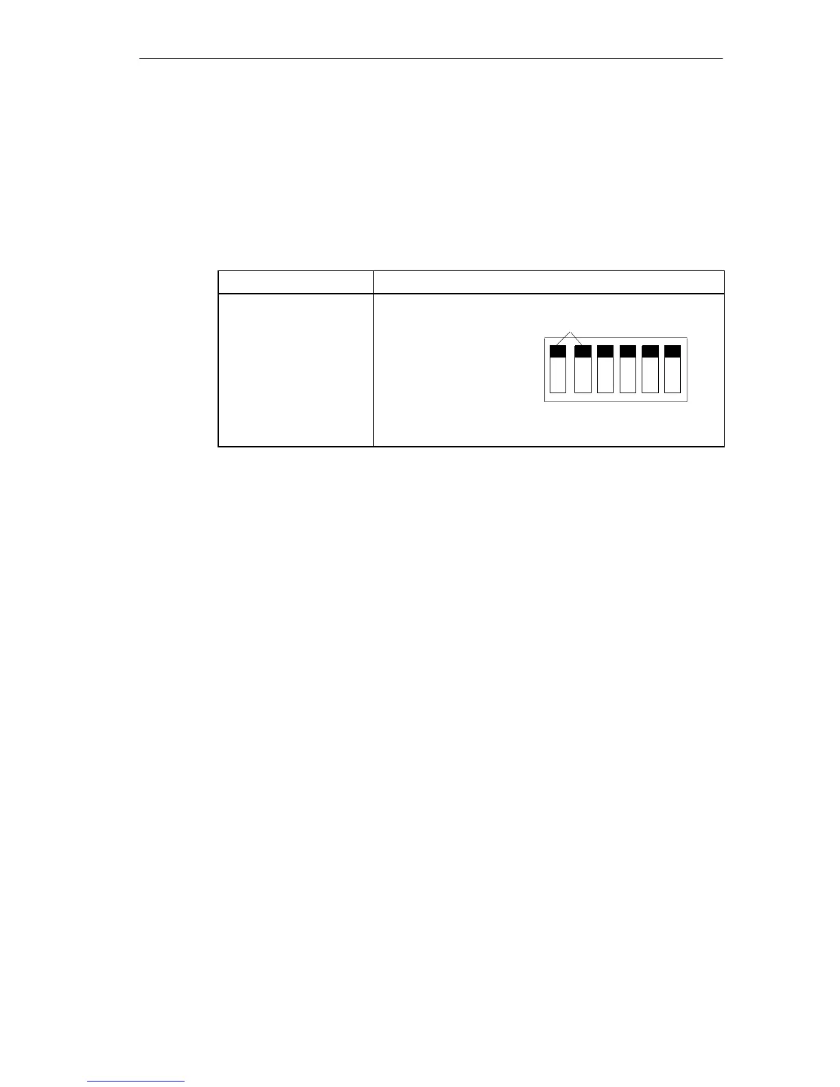
Table 7-5 Settings Address Areas on the IM 314
I/O Area Address
Switch Position
P area: F000 - F0FF
Q area: F100 - F1FF
IM3 area: FC00 - FCFF
IM4 area: FD00 - FDFF
O = OFF, 1 = ON
S1: 0000 *)
0001
1100
1101
OFF
ON
not relevant
*) Status as shipped

Table of Contents

Questions and Answers:

Question and Answer IconNeed help?

Do you have a question about the Siemens Simatic M7-400 and is the answer not in the manual?

Siemens Simatic M7-400 Specifications

General IconGeneral
SeriesSimatic M7-400
ProcessorVaries depending on CPU model (e.g., Intel 80486, Pentium)
Supply voltage24 V DC
Digital inputsVaries depending on I/O module
Digital outputsVaries depending on I/O module
Analog inputsVaries depending on I/O module
Analog outputsVaries depending on I/O module
CommunicationPROFIBUS, PROFINET
Communication PortsMPI, PROFIBUS
Operating Temperature0°C to 60°C

Related product manuals