Digital Modules
4-8
S7-400, M7-400 Programmable Controllers Module Specifications
A5E00069467-07
4.3.2 Parameters of the Digital Output Modules
The parameterized digital output modules use a subset of the parameters and
ranges of values listed in the table below, depending on the functionality. Refer to
the section on the relevant digital module, starting from Section 4.16, to find out
which subset it is capable of using.
The default settings apply if you have not performed parameter assignment in
STEP 7.
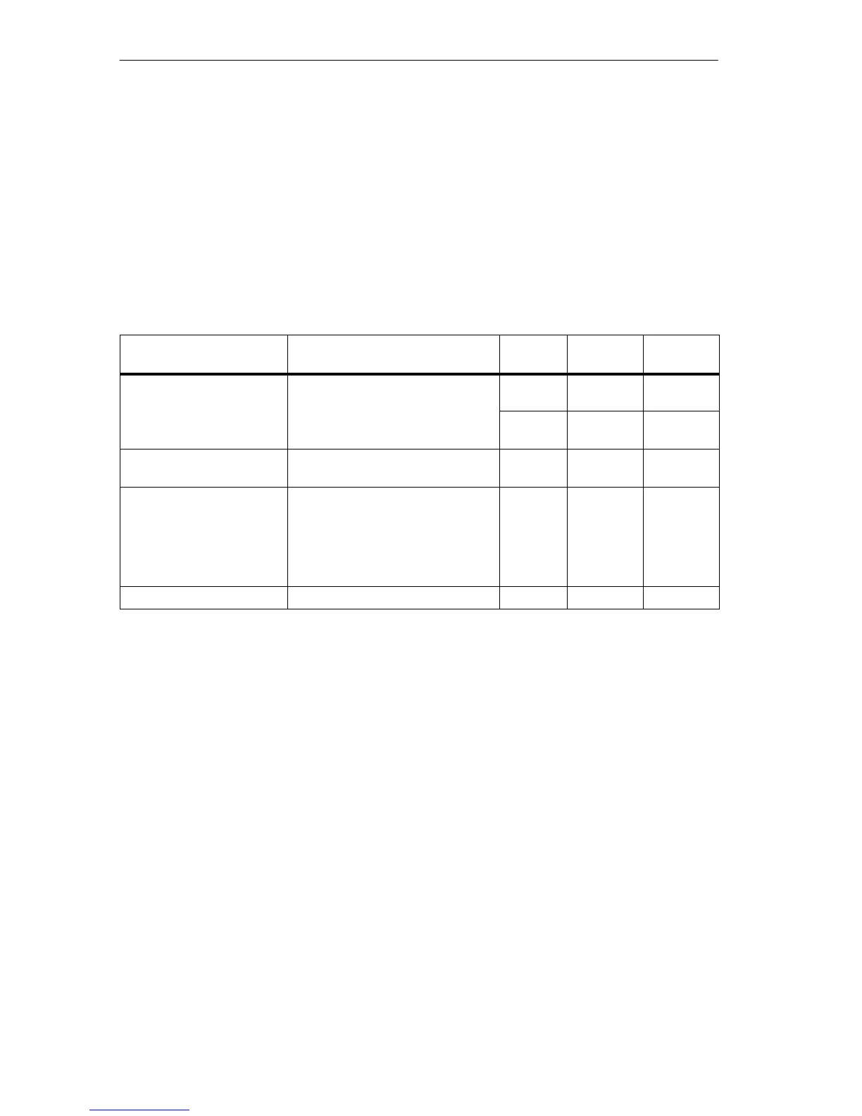
Table 4-7 Parameters of the Digital Output Modules
Parameter
Value Range Default
2)
Parameter
Type
Scope
Enable
• Diagnostic interrupt
1)
Yes/no No Dynamic Module
• Destination CPU for
interrupt
1 to 4
–
Static Module
Reaction to CPU-STOP Substitute a value (SV)
Keep last value (KLV)
SV Dynamic Module
Diagnostics
• Wire break
• No load voltage L+
• Short circuit to M
• Short circuit to L+
• Fuse blown
Yes/no
Yes/no
Yes/no
Yes/no
Yes/no
No
No
No
No
No
Static Channel
Substitute “1” Yes/no No Dynamic Channel
1)
If you use the module in ER-1/ER-2, you must set this parameter to “No” because the interrupt lines are
not available in ER-1/ ER-2.
2)
Only in the CC (central controller) is it possible to start up the digital modules with the default settings and
without support from HWCONFIG.