Digital Modules
4-77
S7-400, M7-400 Programmable Controllers Module Specifications
A5E00069467-07
4.20.1 Assigning Parameters to the SM 422; DO 32 24 VDC/0.5 A
Parameter Assignment
You will find a description of the general procedure for assigning parameters to
digital modules in Section 5.7.
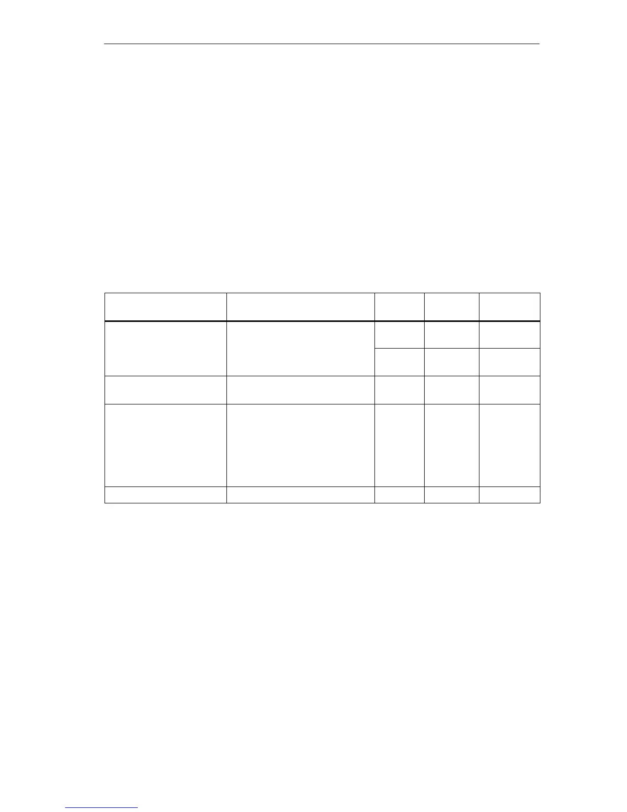
Parameters of the SM 422; DO 32 24 VDC/0.5 A
You will find an overview of the parameters that you can set and their default
settings for the SM 422; DO 32 24 VDC/0.5 A in the table below.
Table 4-18 Parameters of the SM 422; DO 32 24 VDC/0.5 A (6ES7422-7BL00-0AB0)
Parameter
Value Range Default
2)
Parameter
Type
Scope
Enable
• Diagnostic interrupt
1)
Yes/no No Dynamic Module
• Destination CPU for
interrupt
1 to 4
–
Static Module
Reaction to CPU-STOP Substitute a value (SV)
Keep last value (KLV)
SV Dynamic Module
Diagnostics
• Wire break
• No load voltage
L+/sensor supply
• Short circuit to M
• Short circuit to L+
Yes/no
Yes/no
Yes/no
Yes/no
No
no
No
No
Static
Channel
Channel
group
Channel
Channel
Substitute “1” Yes/no No Dynamic Channel
1)
If you use the module in ER-1/ER-2, you must set this parameter to “No” because the interrupt lines are
not available in ER-1/ER-2.
2)
Only in the CC (central controller) is it possible to start up the digital modules with the default settings.

 Loading...


