Interface Modules
6-4
S7-400, M7-400 Programmable Controllers Module Specifications
A5E00069467-07
Rules for Connection
When you connect a central rack to expansion racks, you must observe the
following rules:
• You can connect up to 21 ERs of the S7-400 to one CR.
• The ERs are assigned numbers to identify them. The rack number must be set
on the coding switch of the receive IM. Any rack number between 1 and 21 may
be assigned. Numbers must not be duplicated.
• You may insert up to six send IMs in one CR. However, only two send IMs with
5 V transfer are allowed in one CR.
• Each chain connected to the interface of a send IM can comprise up to four ERs
(without 5 V transfer) or one ER (with 5 V transfer).
• The exchange of data via the communication bus is limited to 7 racks, meaning
the CR and ER numbers 1 to 6.
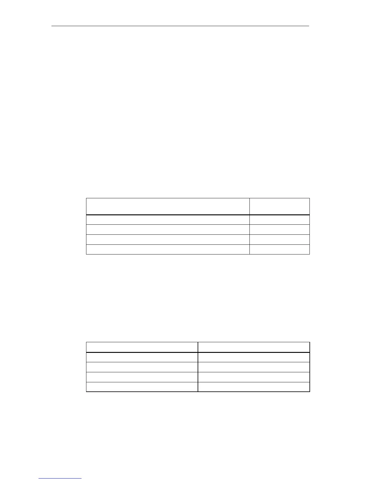
• The maximum (total) cable lengths specified for the type of connection must not
be exceeded.
Connection type Maximum (total) line
length
Local connection with 5 V transfer via IM 460-1 and IM 461-1 1.5 m
Local connection without 5 V transfer via IM 460-0 and IM 461-0 3 m
Remote connection via IM 460-3 and IM 461-3 102.25 m
Remote connection via IM 460-4 and IM 461-4 605 m
Terminator
The bus must be terminated in the last EU of a line. To do this, plug in the
appropriate terminator in the lower front connector of the receive IM in the last EU
of the line. Unused front connectors in a send IM do not have to be terminated. The
IM 461-1 with the order number 6ES7 461-1BA01-0AA0 does not require a
terminator.
Table 6-2 Terminators for the Receive IMs
Receive IM
Terminator
IM 461-0 6ES7461-0AA00-7AA0
IM 461-1 6ES7461-1BA00-7AA0
IM 461-3 6ES7461-3AA00-7AA0
IM 461-4 6ES7461-4AA00-7AA0