General Technical Specifications
1-10
S7-400, M7-400 Programmable Controllers Module Specifications
A5E00069467-07
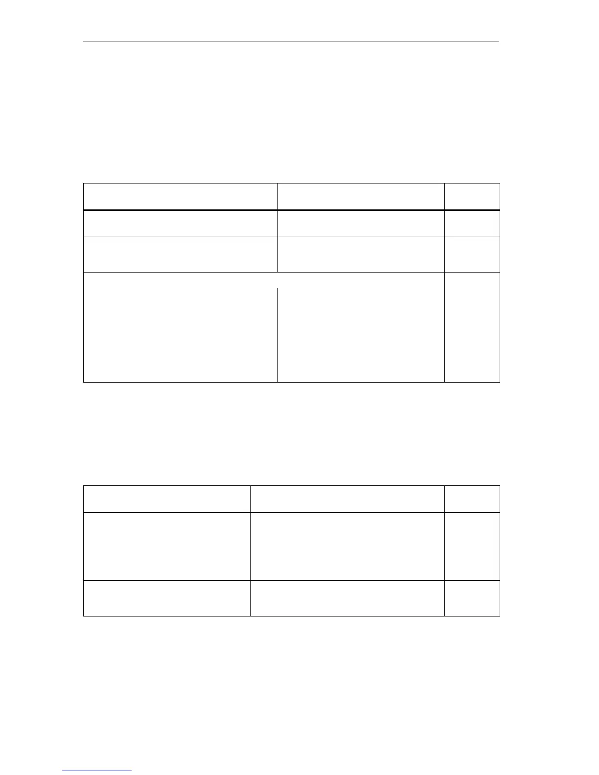
Pulse-Shaped Interference
The following table shows the electromagnetic compatibility of modules when there
are pulse-shaped disturbance variables. A requirement for this is that the
S7-400/M7-400 system complies with the relevant requirements and guidelines on
electric design.
Table 1-4 Pulse-Shaped Interference
Pulse-Shaped Interference
Test Voltage Degree of
Severity
Electrostatic discharge
To IEC 61000-4-2
Discharge to air: ±8 kV
Contact discharge: ±6 kV
3
Bursts (fast transient interference in accor-
dance with IEC 61000-4-4)
2 kV (power supply line)
2 kV (signal line > 30 m)
1 kV (signal line < 30 m)
3
Energy-rich single impulse (surge) to IEC 61000-4-5 3
• Asymmetrical coupling 2 kV (supply line) DC voltage with
protective elements
2 kV (signal line/data line > 30 m only),
possibly with protective elements
• Symmetrical coupling 1 kV (supply line) DC voltage with
protective elements
1 kV (signal line > 30 m only), possibly
with protective elements
Sinusoidal Interference
The following table shows you the EMC behavior of the S7-400/M7-400 modules
when there is sinusoidal interference.
Table 1-5 Sinusoidal Interference
Sinusoidal Interference
Test Values Degree of
Severity
RF irradiation (electromagnetic fields)
To IEC 61000-4-3
To IEC 61000-4-3
10 V/m with 80% amplitude modulation of
1 kHz over the range from 80 MHz to
1000 MHz
10 V/m with 50% pulse modulation at 900 MHz
3
RF conductance on cables and cable
shields to IEC 61000-4-6
Test voltage 10 V with 80% amplitude
modulation of 1 kHz over the range from 9 MHz
to 80 MHz
3