IM 463-2
7-5
S7-400, M7-400 Programmable Controllers Module Specifications
A5E00069467-07
LEDs
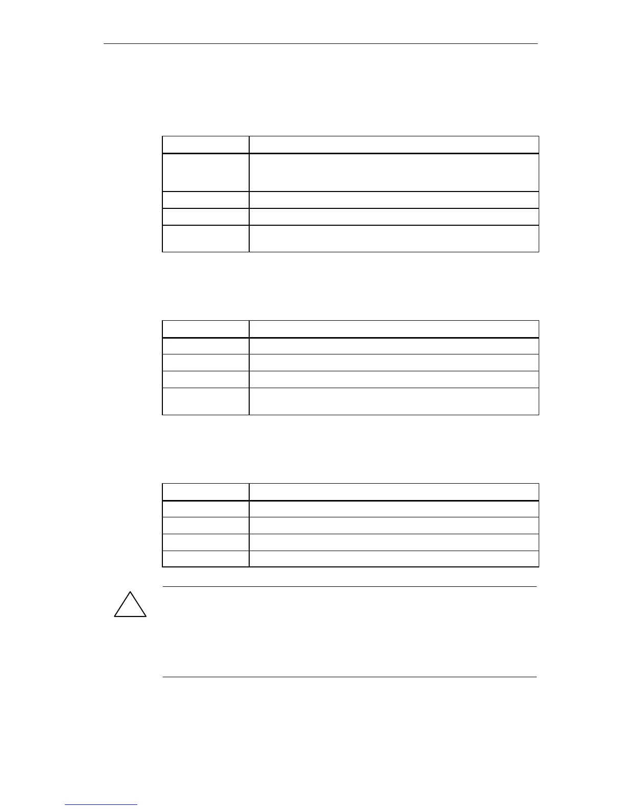
Table 7-2 LEDs of the IM 4632
LED
Meaning
LED EXTF (red) Lights up in the event of an external fault. Chain 1 or chain 2 has a
fault (power supply failed in the EU; terminating connector missing;
wire break, or interface selector switch wrongly set).
LED C1 (green) Chain 1 (via front connector X1, connection 1) is in order.
LED C2 (green) Chain 2 (via front connector X2, connection 2) is in order.
Front connector X1
and X2
Connector plug (output) for chain 1 and chain 2.
X1 = upper front connector; X2 = lower front connector
Interface Selector Switch
Table 7-3 LEDs of the IM 463-2
Switch Position
Meaning
C1 ON You use only interface C1.
C2 ON You use only interface C2.
C1, C2 ON You use both interfaces.
C1, C2 OFF You use neither of the two interfaces.
You do not want to operate an S5 EU at present.
Cable Length Selector Selector
Table 7-4 Switch Position: Interface Selector of the IM 463-2
Switch Position
Meaning
100 Cable length 1 to 100 m
250 Cable length 100 to 250 m
450 Cable length 250 to 450 m
600 Cable length 450 to 600 m
!
Warning
Danger of data loss.
Changing the setting of the interface selector switch and the cable length selector
switch in RUN mode can result in loss of data.
Change the settings of these switches only in STOP mode of the CPU.

 Loading...


