RS 485 Repeater
10-3
S7-400, M7-400 Programmable Controllers Module Specifications
A5E00069467-07
10.2 Appearance of the RS 485 Repeater;
(6ES7972-0AA01-0XA0)
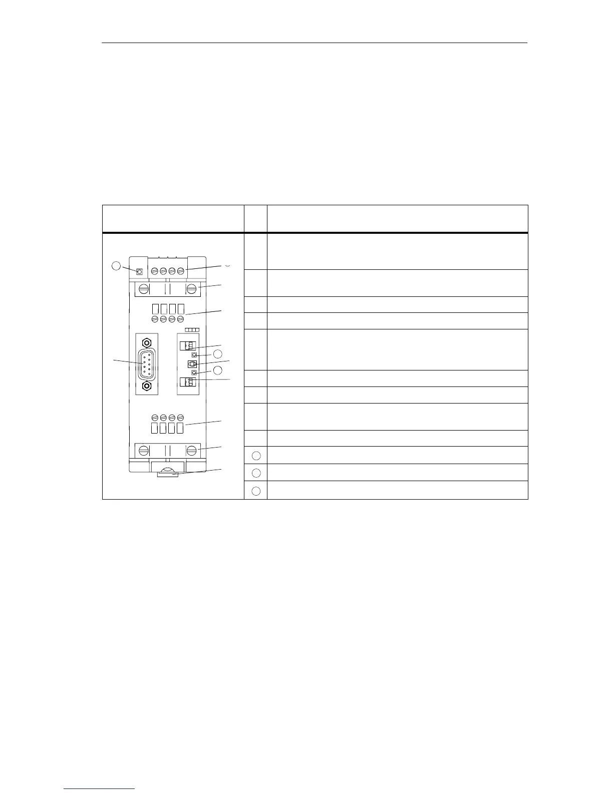
The table below shows the appearance of the RS 485 repeater and lists its
functions.
Table 10-3 Description and Functions of the RS 485 Repeater
Repeater Design
No
.
Function
24 VDC
L+ M PE M 5.2
À
10
À Connection for the RS 485 repeater power supply (pin “M5.2” is
the ground reference, if you want to measure the voltage
difference between terminals “A2” and “B2”).
Á
Á Shield clamp for the strain relief and grounding of the bus cable
of bus segment 1 or bus segment 2
Â
 Terminals for the bus cable of bus segment 1
A1 B1 A1 B1
à Terminating resistance for bus segment 1
Ã
Ä
È
PG
11
OFF
ON
DP1
Ä Switch for OFF operating mode
(= isolate bus segments from each other – for example, for
startup
Å
OP
DP2
12
Å Terminating resistance for bus segment 2
SIEMENS
ON
Æ Terminals for the bus cable of bus segment 2
RS 485-REPEATER
Æ
A2 B2 A2 B2
Ç Slide for mounting and removing the RS 485 repeater on the
standard rail
È Interface for programming device/OP in bus segment 1
10
LED 24 V supply voltage
Ç
11
LED for bus segment 1
12
LED for bus segment 2