CPUs for M7-400
11-41
S7-400, M7-400 Programmable Controllers Module Specifications
A5E00069467-07
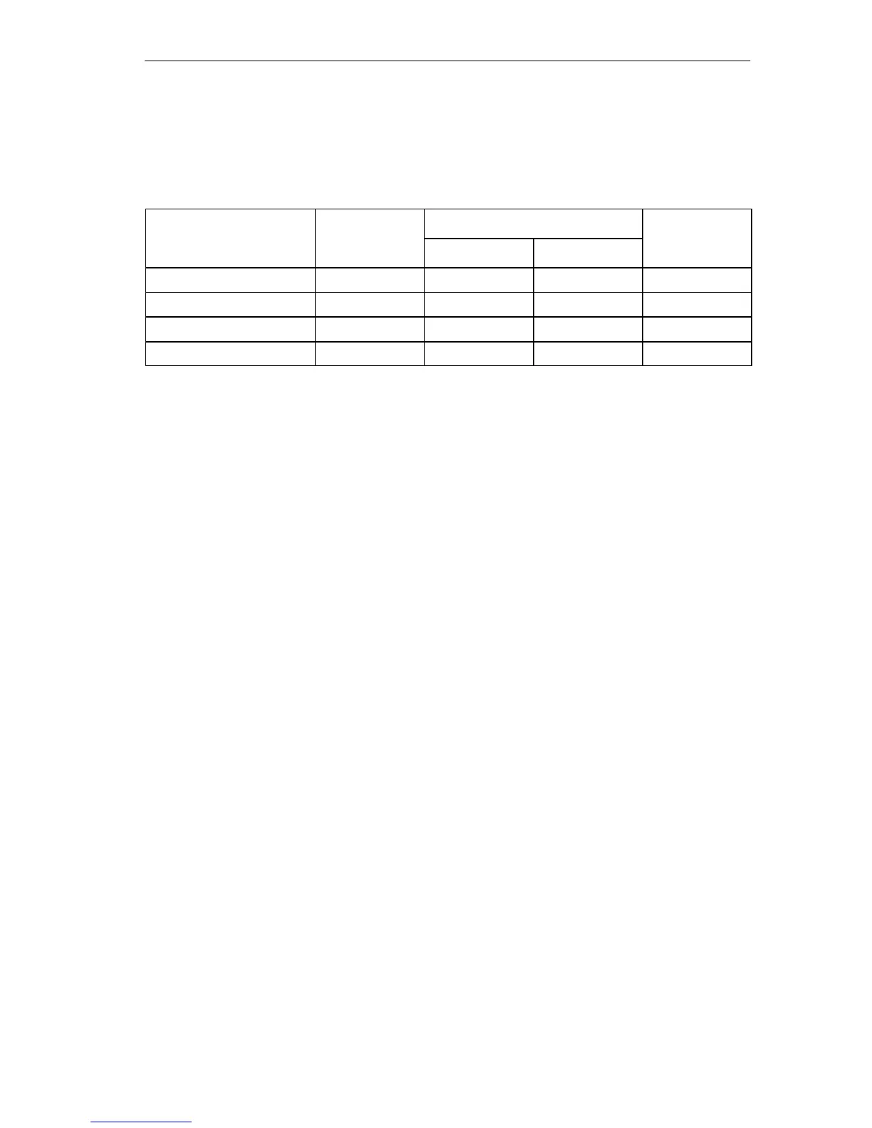
Memory Areas for AT Cards
AT cards which are inserted in the expansion module ATM 478 can occupy the
following memory areas:
Range M7 RMOS32
M7 RMOS32 with MS-DOS
M7 RMOS32
Without EMS With EMS
w
t
MS-Windows
D 0000H to E 7FFFH 96 K 96 K 32 K
2)
32 K
2)
C 8000H to C BFFFH 16 K 16 K 16 K 16 K
C C000H bis C EFFFH
1)
12 K 12 K 12 K 12 K
C F000H to C FFFFH 4 K 4 K 4 K 4 K
1)
The area is only available if no memory card is present.
2)
Under M7 RMOS32 with MS Windows, or if the driver software under MS-DOS requires
expanded memory (EMS), the memory manager EMM386 occupies 64K in the area
D0000H to E7FFFH because it must be operated in EMS mode.
I/O Address Area
Addressing the ISA-compatible input/output components is done in the I/O area
under the addresses from 0100
H
to 03FFH. The addresses specified by the ISA
architecture are used here. In contrast to the original AT, the I/O addresses in the
CPUs are completely decoded so that the addresses above 03 FFH can be used
for addressing M7-400-specific hardware.
I/O Address Area for AT Adapter Modules
If you are using AT adapter modules, the following address areas are available for
addressing:
• 0200
H
to 03FF
H
• Except for the area 3 E0H to 3 E3H and
• Except for the areas which the interface submodules are occupying (see the
“Interface Submodules” chapter).

 Loading...


