M7-400 Expansions
12-10
S7-400, M7-400 Programmable Controllers Module Specifications
A5E00069467-07
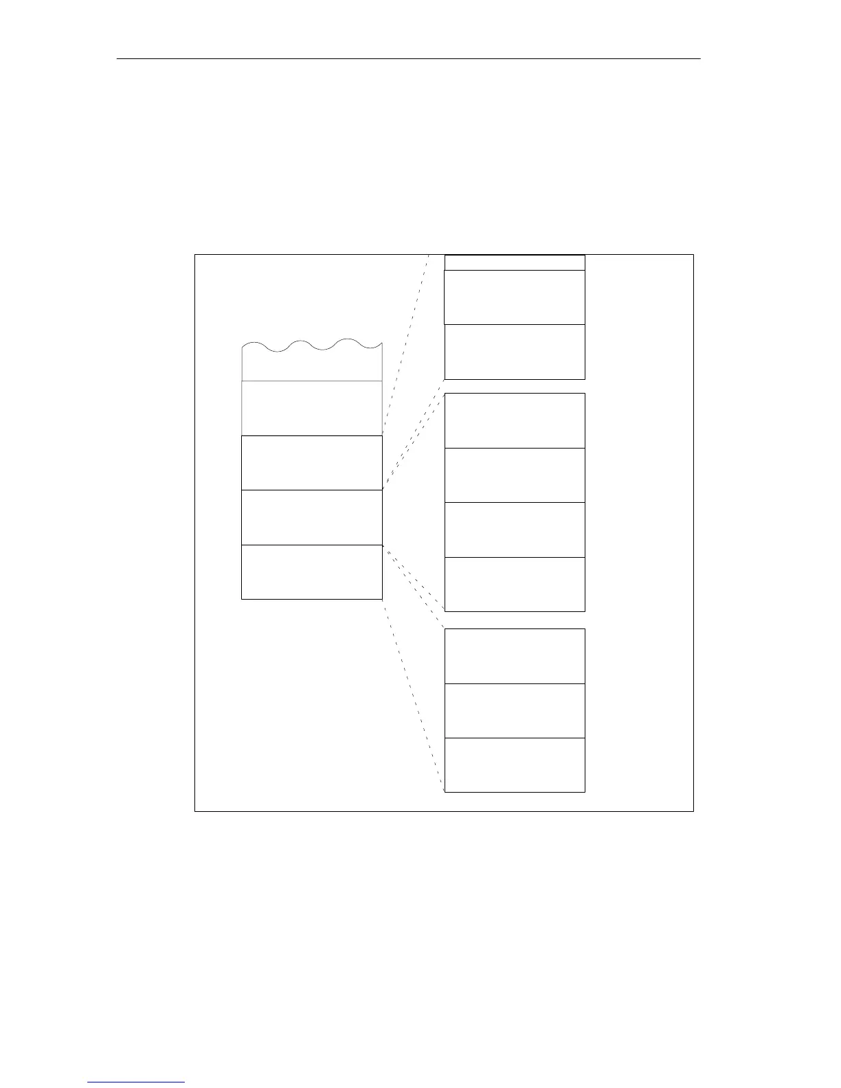
Division of Addresses in the M7-400-Specific I/O Address Area
The EXM 478 expansion module is operated on the ISA bus of the programmable
module. The I/O address area from C000
H
(to D2FF
H
) in the CPU 486-3,
CPU 488-3, or the FM 456 application module is reserved for this purpose. Each
expansion module occupies 256 bytes (100
H
) in this area. The division of the
address area is shown in Figure 12-6 using the FM 456-4 as an example.
Cn00
Co00
Cp00
Cq00
2) EXM 478
expansion module
Submodule receptacle
number 1
Reserved
00
40
80
All addresses are in hexadecimal notation.
Submodule receptacle
number 5
Submodule receptacle
number 4
Submodule receptacle
number 3
00
40
80
C0
FF
1) EXM 478
expansion module
e.g. FM 456-4
Cr00
3) EXM 478
expansion module
Submodule receptacle
number 0
Reserved
Submodule receptacle
number 6
00
40
80
Reserved
n .. q =Number of the slot of the
module in the mounting
rack
(in hexadecimal notation)
Example:
n = 6 FM 456-4 C600H
o = 7 1) EXM 478 C700H
p = 8 2) EXM 478 C800H
q = 9 3. EXM 478 C900H
BF
Figure 12-6 Base Addresses of the Expansion Modules and the Interface Submodules

 Loading...


