M7-400 Expansions
12-12
S7-400, M7-400 Programmable Controllers Module Specifications
A5E00069467-07
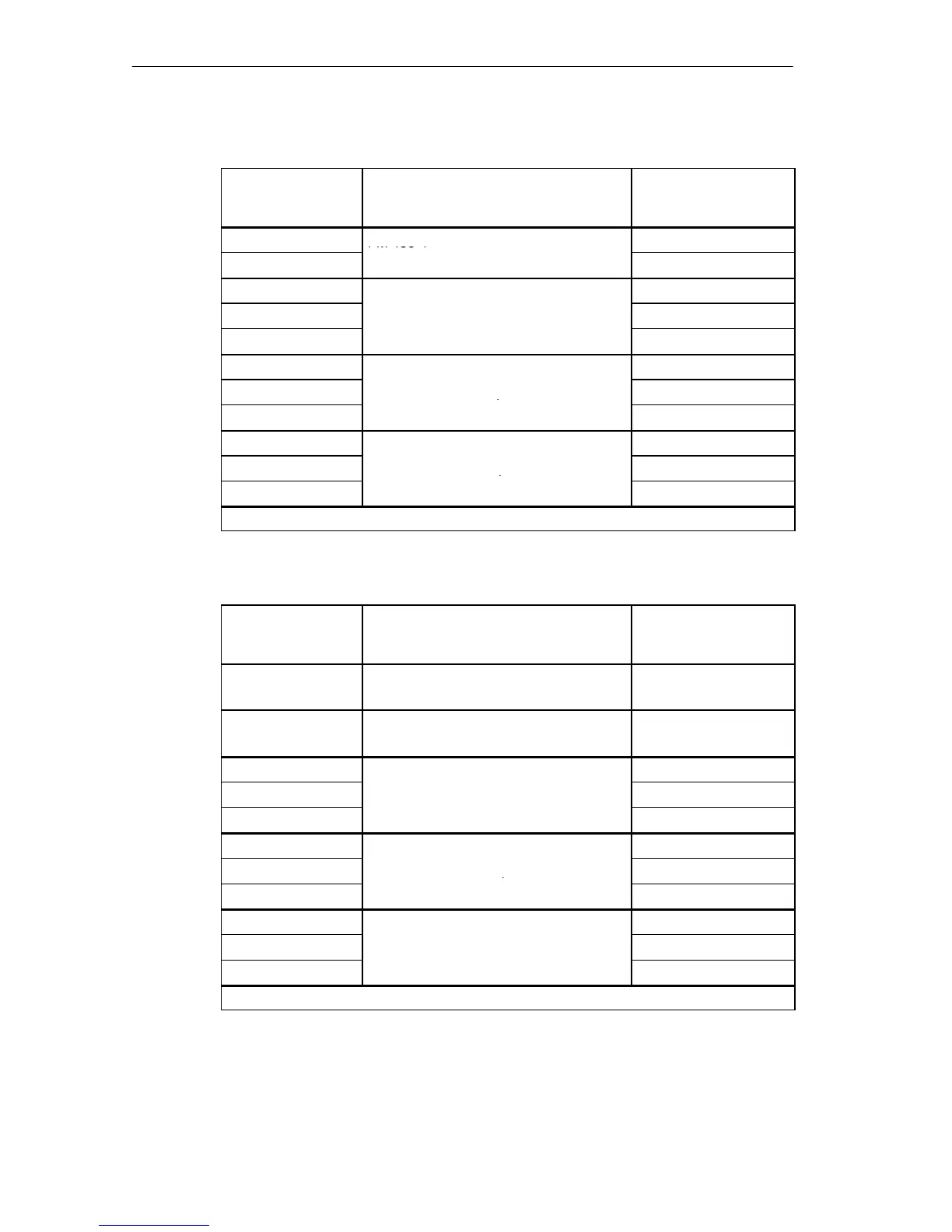
Table 12-3 Base Addresses of the Interface Submodules with FM 456-4
Base Address
Modules
Interface Submodule
in Submodule
Receptacle ...
Cn40
H
FM 456-4
Number 0
Cn80
H
Slot n
Number 1
Co40
H
Nummer 3
Co80
H
1st EXM 478 in slot o = n + 1
Number 4
CoC0
H
Number 5
Cp40
H
Number 6
Cp80
H
2nd EXM 478 in slot p = n + 2
Number 7
CpC0
H
Number 8
Cq40
H
Number 9
Cq80
H
3rd EXM 478 in slot q = n + 3
Number 10
CqC0
H
Number 11
n .. q = Number of the module slot in the mounting rack in hexadecimal notation.
Table 12-4 Base Addresses of the Expansion Modules with CPU 486-3,
CPU 488-3
Base Address
Modules
Interface Submodule
in Submodule
Receptacle ...
Cn40
H
CPU 486-3, CPU 488-3
Slot n
Number 0
Co40
H
CPU 486-3, CPU 488-3
Slot o = n + 1
Nummer 3
Cp40
H
Number 6
Cp80
H
1st EXM 478 in slot p = n + 2
Number 7
CpC0
H
Number 8
Cq40
H
Number 9
Cq80
H
2nd EXM 478 in slot q = n + 3
Number 10
CqC0
H
Number 11
Cr40
H
Number 12
Cr80
H
3rd EXM 478 in slot r = n + 4
Number 13
CrC0
H
Number 14
n .. r = Number of the module slot in the mounting rack in hexadecimal notation.

 Loading...


