Interface Submodules
13-20
S7-400, M7-400 Programmable Controllers Module Specifications
A5E00069467-07
Default Settings in the BIOS
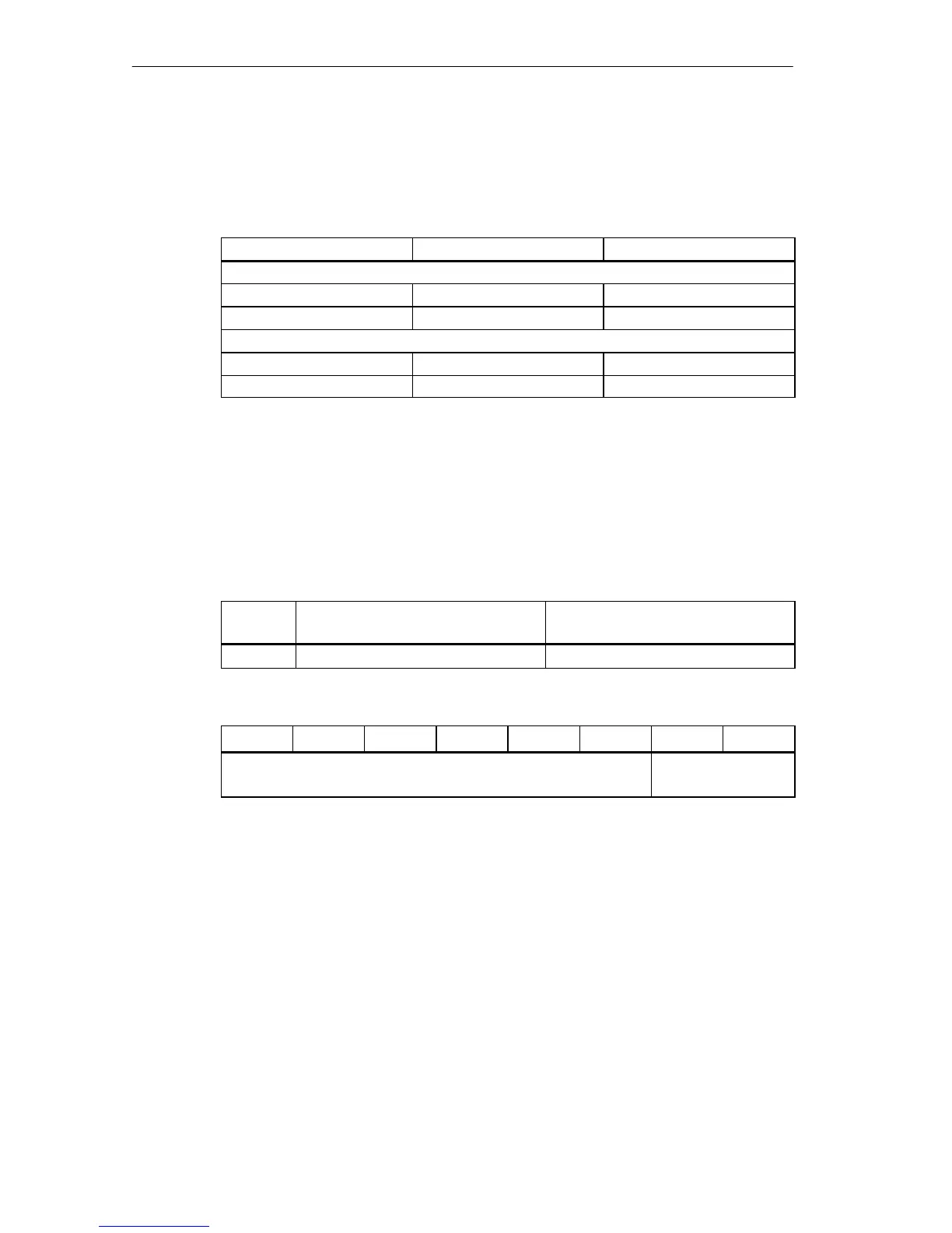
The following I/O addresses and interrupt numbers are set as defaults in the BIOS
for LPT ports:
Port I/O Address Interrupt No.
With mass storage module MSM 478
LPT1 (on MSM 478) 03BCH 7
LPT2 (IF 962-LPT) 0378H 5
Without mass storage module MSM 478
LPT1 (IF 962-LPT) 0378H 7
LPT2 (IF 962-LPT) 0278H 5
Configuration register
The BIOS setup defines in which AT-compatible I/O address area the LPT interface
is to be operated or whether it is only to be operated in the reserved I/O address
area and this information is stored in the configuration register. Tables 13-18 to
13-20 give you an overview of the possible settings in the configuration register.
Table 13-18 Offset Address for the Configuration Register (IF 962-LPT)
Offset
Address
Function Remarks
0
H
Configuration register Read/write
Table 13-19 Meaning of the Data Bits in the Configuration Register (IF 962-LPT)
Bit 7
Bit 6 Bit 5 Bit 4 Bit 3 Bit 2 Bit 1 Bit 0
Write: Any (“0” or “1”)
Read: Always “1”
Addressing type LPT