Interface Submodules
13-63
S7-400, M7-400 Programmable Controllers Module Specifications
A5E00069467-07
13.9.1 Pin Assignments
X1 Connector
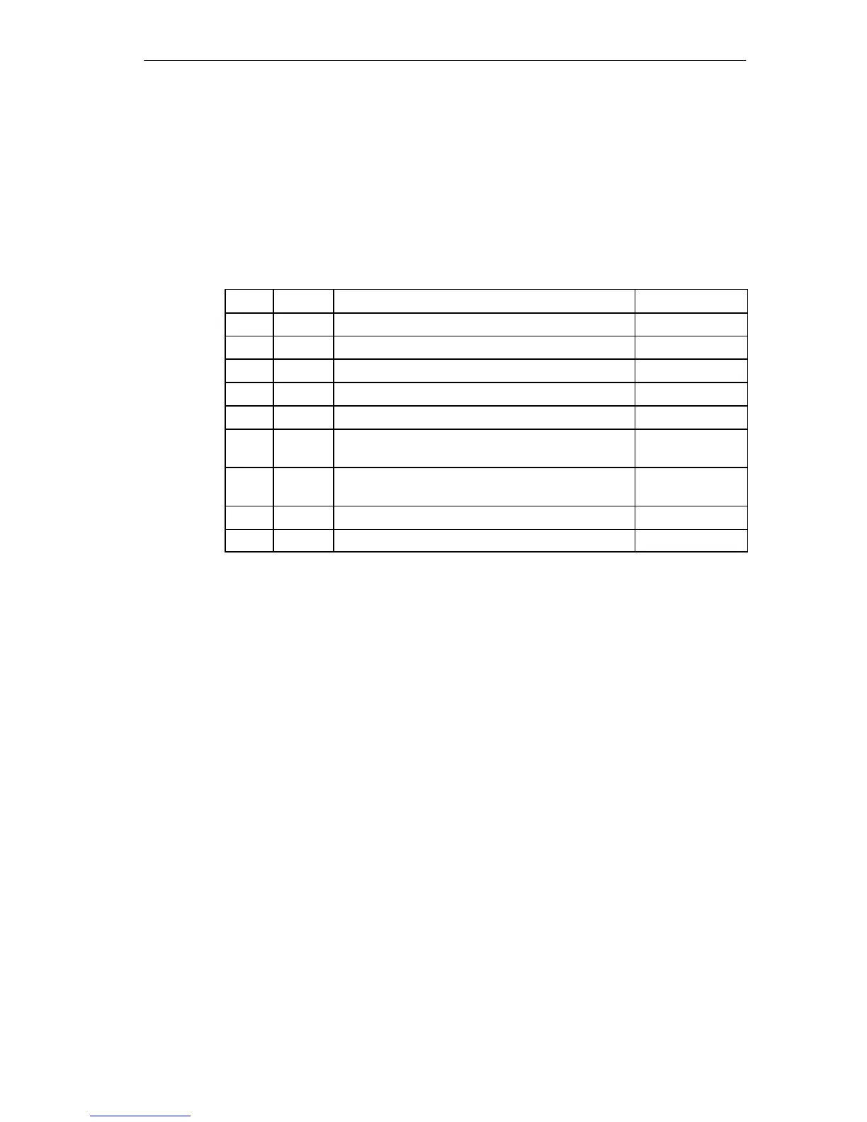
There is a 9-pin sub D socket connector on the frontside of the submodule for
plugging in the connecting cable. See Table 13-45 for the pin assignments.
Table 13-45 X1 Socket, IF 964-DP (9-Pin Sub D Connector)
Pin
Signal Meaning Direction
1 –
2 M 24 24 V reference potential (6ES7 964-2AA01-0AB0) Output
3 LTG_B Line B Input/Output
4 RTSAS Request to send (AS) Output
5 M5
ext
Operational ground (isolated) Output
6 P5
ext
+ 5 V (isolated), max. 20 mA
(for supplying the bus terminator)
Output
7 P 24 V +24 V, max. 150 mA, non-isolated
(6ES7 964-2AA01-0AB0)
Output
8 LTG_A Line A Input
9 –
What Can be Connected to the Interface Submodule?
Devices with PROFIBUS can be connected, such as the following:
ET 200 M, ET 200 U (B/C) and other devices conforming to the standard.
Additional S7 DP masters (PG, OP)

 Loading...


