Diagnostic Data of the Signal Modules
B-13
S7-400, M7-400 Programmable Controllers Module Specifications
A5E00069467-07
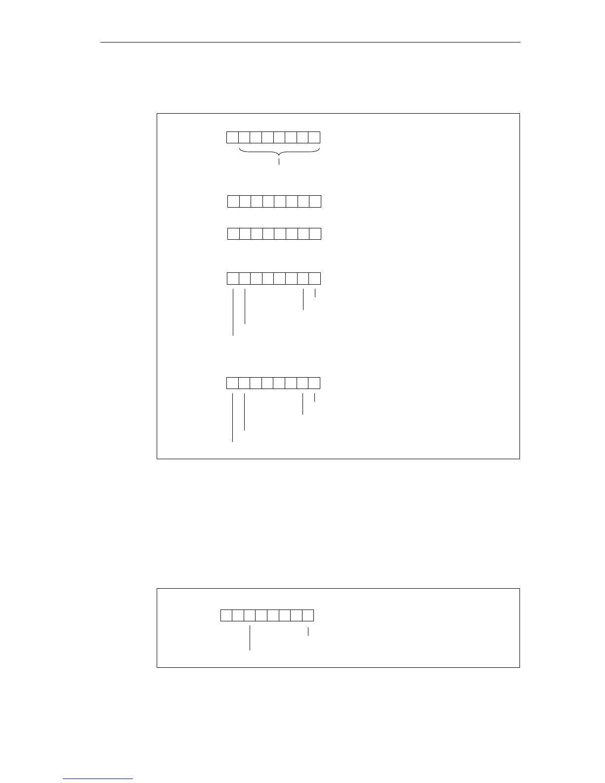
Bytes 4 to 8 of the SM 422; DO 16 20-120 VAC/2 A
Byte 4
76 054321
Byte 5
70
Channel type B#16#72: digital output
Number of diagnostics bits that the module
outputs per channel: 8 bits long
Byte 6
70
Number of channels of the same
type in one module: 16 channels
0
Byte 7
76 0
Channel error, channel 0
Channel error, channel 1
Channel error, channel 6
Channel error, channel 7
54321
...
Byte 8
76 0
Channel error, channel 14
Channel error, channel 15
54321
...
Channel error, channel 8
Channel error, channel 9
Figure B-15 Bytes 4 to 8 of the Diagnostic Data of the SM 422; DO 16 x 20-120 VAC/2 A
Bytes 9 to 24 of the SM 422; DO 16 20-120 VAC/2 A
Data record 1 with bytes 9 to 24 contains the channel-specific diagnostic data. The
figure below shows the assignment of the diagnostic byte for a channel of the
module.
76 0
Fuse blown
54321
0
Configuring/parameter assignment error
00000
Figure B-16 Diagnostic Byte for a Channel of the SM 422; DO 16 x 20-120 VAC/2 A