Diagnostic Data of the Signal Modules
B-15
S7-400, M7-400 Programmable Controllers Module Specifications
A5E00069467-07
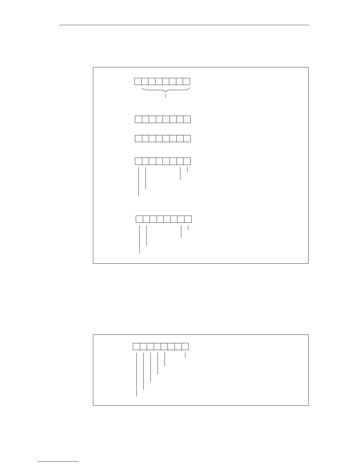
Bytes 4 to 8 of the SM 431; AI 16 16 Bit
Byte 4
76 054321
Byte 5
70
Channel type B#16#71: analog input
Number of diagnostics bits that the module
outputs per channel: 8 bits long
Byte 6
70
Number of channels of the same
type in one module: 16 channels
Byte 7
76 0
Channel error, channel 0
Channel error, channel 1
Channel error, channel 6
Channel error, channel 7
54321
...
0
Byte 8
76 0
Channel error, channel 14
Channel error, channel 15
54321
...
Channel error, channel 8
Channel error, channel 9
Figure B-18 Bytes 4 to 8 of the Diagnostic Data of the SM 431; AI 16 x 16 Bit
Bytes 9 to 24 of the SM 431; AI 16 x 16 Bit
Data record 1 with bytes 9 to 24 contains the channel-specific diagnostic data. The
figure below shows the assignment of the diagnostic byte for a channel of the
module.
76 0
Configuring/parameter assignment error
Wire break
Underflow
Overflow
54321
Short-circuit to M
Reference channel error
00
Figure B-19 Diagnostic Byte for a Channel of the SM 431; AI 16 x 16 Bit

 Loading...


