D-8
SIMATIC TD 200 Operator Interface
C79000-G7076-C272-01
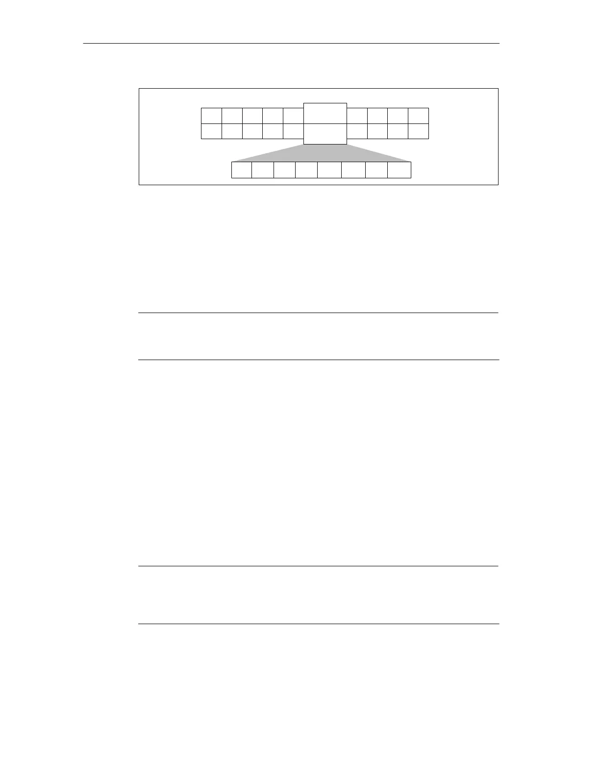
M Area Address
F4 F3 F2 F1
Shift
F4
Shift
F3
Shift
F2
Shift
F1
MBn
MSB
7
654 3 21
LSB
0
1 2 4 6 7 8 9
Byte 5
M
Offset
30
Figure D-6 Bits Set by Each Function Key
Message Address Bytes 6 and 7
Bytes 6 and 7 of the TD 200 parameter block define an integer-word offset in
V memory where the TD 200 looks for the first message. Valid offset values for
specific CPUs are defined in the
SIMATIC S7-200 Programmable Controller
System Manual
.
Note
Each 20-character message uses 20 VB memory locations; each 40-character
message uses 40 VB memory locations.
Message-Enable Address Bytes 8 and 9
Bytes 8 and 9 of the TD 200 parameter block define the integer-word offset in V
memory where the TD 200 looks for the first byte of the message-enable bits. Valid
offset values for specific CPUs are defined in the
SIMATIC S7-200 Programmable
Controller System Manual
.
For example: if you assign VB50 as the message-enable address, the first
message is enabled by bit V50.7, the second message by V50.6, the third
message by V50.5, and the eighth message by V50.0.
You must not use message-enable bits for any purpose other than enabling
messages. The TD 200 requires that you allocate full bytes for message-enable
bits.
Note
You can set or clear the message-enable bits from within your program. The
TD 200 may also clear the message-enable bit following an acknowledge or an
edit. See Section D.6 for more information.
TD 200 Parameters and Messa
es

 Loading...