1-6
SIMATIC TD 200 Operator Interface
C79000-G7076-C272-01
1.2 Installing the TD 200
Preparing the Mounting Surface
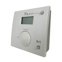
Cut a 138 mm x 68 mm (or 5.44 in. x 2.7 in.) hole in the mounting surface
(DIN 43700). Figure 1-5 shows the mounting surface cutout dimensions. Refer to
Appendix A for outside dimensions.
138 mm
(5.44 in.)
68 mm
(2.7 in.)
Figure 1-5 Mounting Surface Hole Dimensions
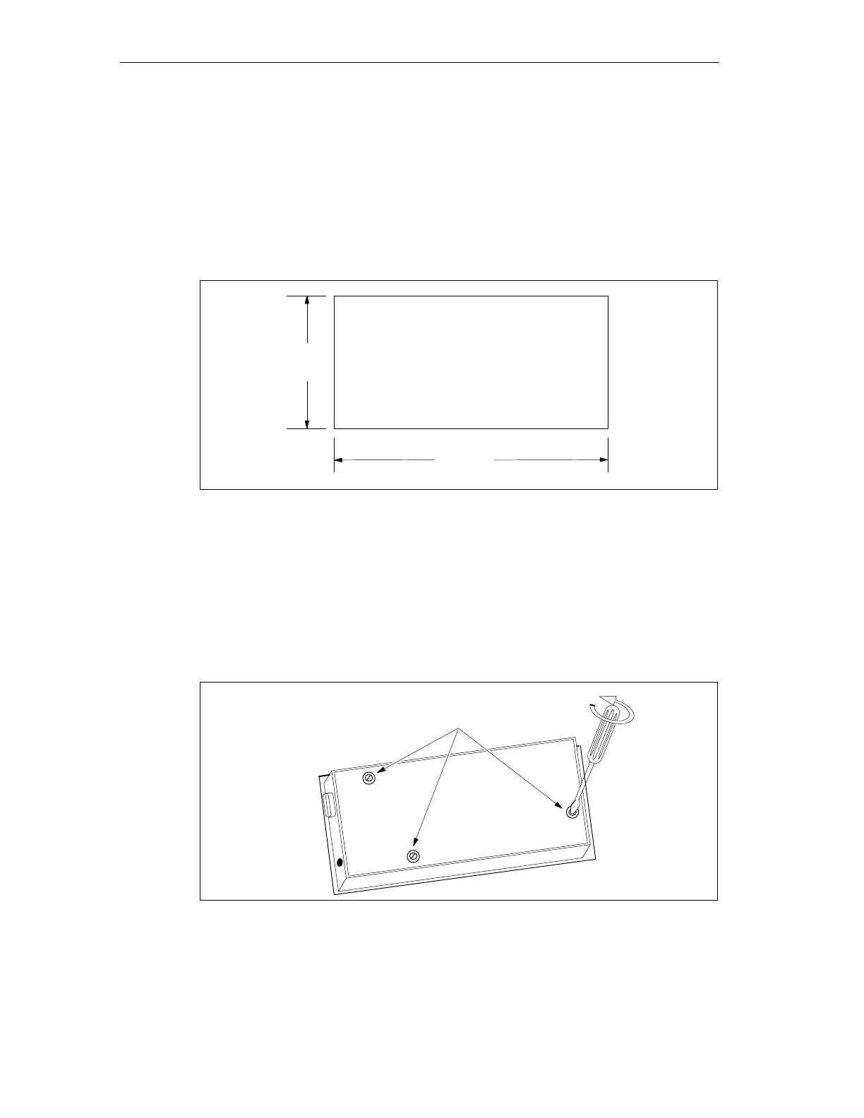
Preparing the TD 200 for Mounting
Use the following steps to prepare the TD 200 for mounting.
1. Remove the three screws from the rear of the TD 200 using a flat-head
screwdriver or a T8 Torx screwdriver. See Figure 1-6.
2. Remove the backplate of the TD 200.
Mounting
Screws
Figure 1-6 Removing the Three Mounting Screws
Product Overview and Installation