B-6
SIMATIC TD 200 Operator Interface
C79000-G7076-C272-01
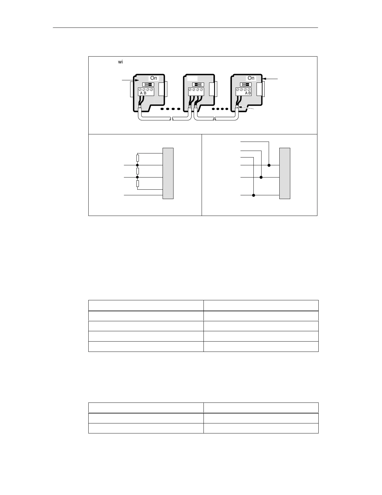
ABAB
ABAB
On On
ABAB
Off
Switch position = On
Terminated and biased
Switch position = Off
No termination or bias
Switch position = On
Terminated and biased
Cable must be
terminated and biased
at both ends.
Interconnecting cable
390 Ω
220 Ω
390 Ω
B
A
TxD/RxD +
TxD/RxD -
Cable shield
6
3
8
5
1
Network
connector
Pin #
B
A
TxD/RxD +
TxD/RxD -
Cable shield
Network
connector
A
B
Switch position = Off
No termination or bias
TxD/RxD +
TxD/RxD -
Cable shield
Switch position = On
Terminated and biased
Bare shielding
(~12 mm or 1/2 in.) must
contact the metal guides
of all locations.
6
3
8
5
1
Pin #
Network
connector with
programming
port
Network
connector
Figure B-4 Bias and Termination of Interconnecting Cable
Cable for a PROFIBUS Network
Table B-1 lists the general specifications for a PROFIBUS network cable (order
number 6XVI 830–0AH10).
Table B-1 General Specifications for a PROFIBUS Network Cable
General Features
Specification
Type Shielded, twisted pair
Conductor cross section 24 AWG (0.22 mm
2
) or larger
Cable capacitance < 60 pF/m
Nominal impedance 100 Ω to 120 Ω
The maximum length of a PROFIBUS network segment depends on the baud rate
and the type of cable used. Table B-2 lists the maximum segment lengths for cable
matching the specifications listed in Table B-1.
Table B-2 Maximum Cable Length of a Segment in a PROFIBUS Network
Transmission Rate
Maximum Cable Length of a Segment
9.6 kbaud to 19.2 kbaud 1,200 m (3,936 ft.)
187.5 kbaud 1,000 m (3,280 ft.)
Multiple CPU Confi
urations