Mounting, wiring, connecting, system interfaces, configuration guidelines
12.2 Wiring, connecting
SIMOCODE pro
200 System Manual, 05/2019, A5E40507475002A/RS-AD/004
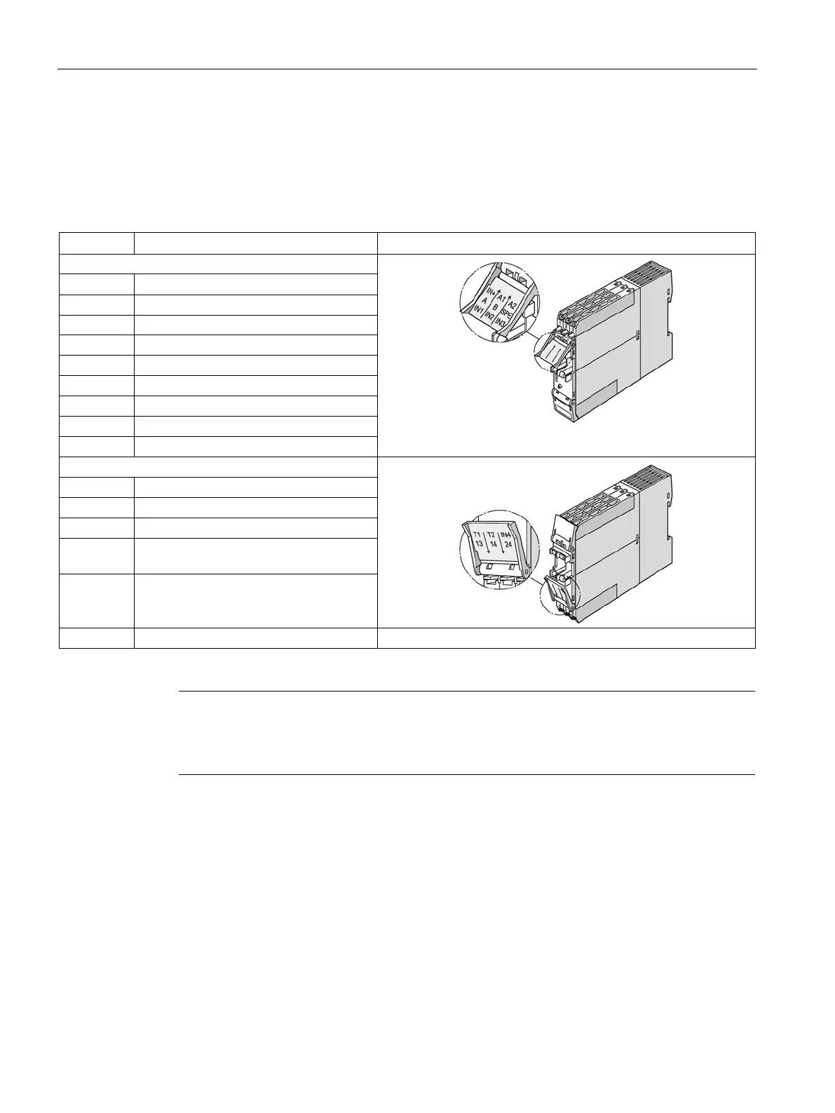
Assignment of the removable terminals, SIMOCODE pro S basic units
The following table shows the assignment of the removable terminals of the
SIMOCODE pro S basic unit:
Table 12- 6 Assignment of the removable terminals, SIMOCODE pro S basic unit
IN+ 24 V DC only for IN1 to IN4
Supply voltage terminal 1
Supply voltage terminal 2
1)
Thermistor connection 1 (binary PTC)
Thermistor connection 2 (binary PTC)
13 Common potential for relay outputs 1
14 Relay output OUT1
1)
pro via terminal SPE with the maximum possible cross-section and
with as short a cable as possible to the func
tional ground of the control cabinet, e.g. to the
grounded mounting plate of the control cabinet.