8
Tool Offsets 04.00
8.5 Activate 3D tool offsets
8
840D
NCU 572
NCU 573
840Di
Siemens AG 2000. All rights reserved
8-280
SINUMERIK 840D/840Di/810D/FM-NC Programming Guide Advanced (PGA)
−
04.00 Edition
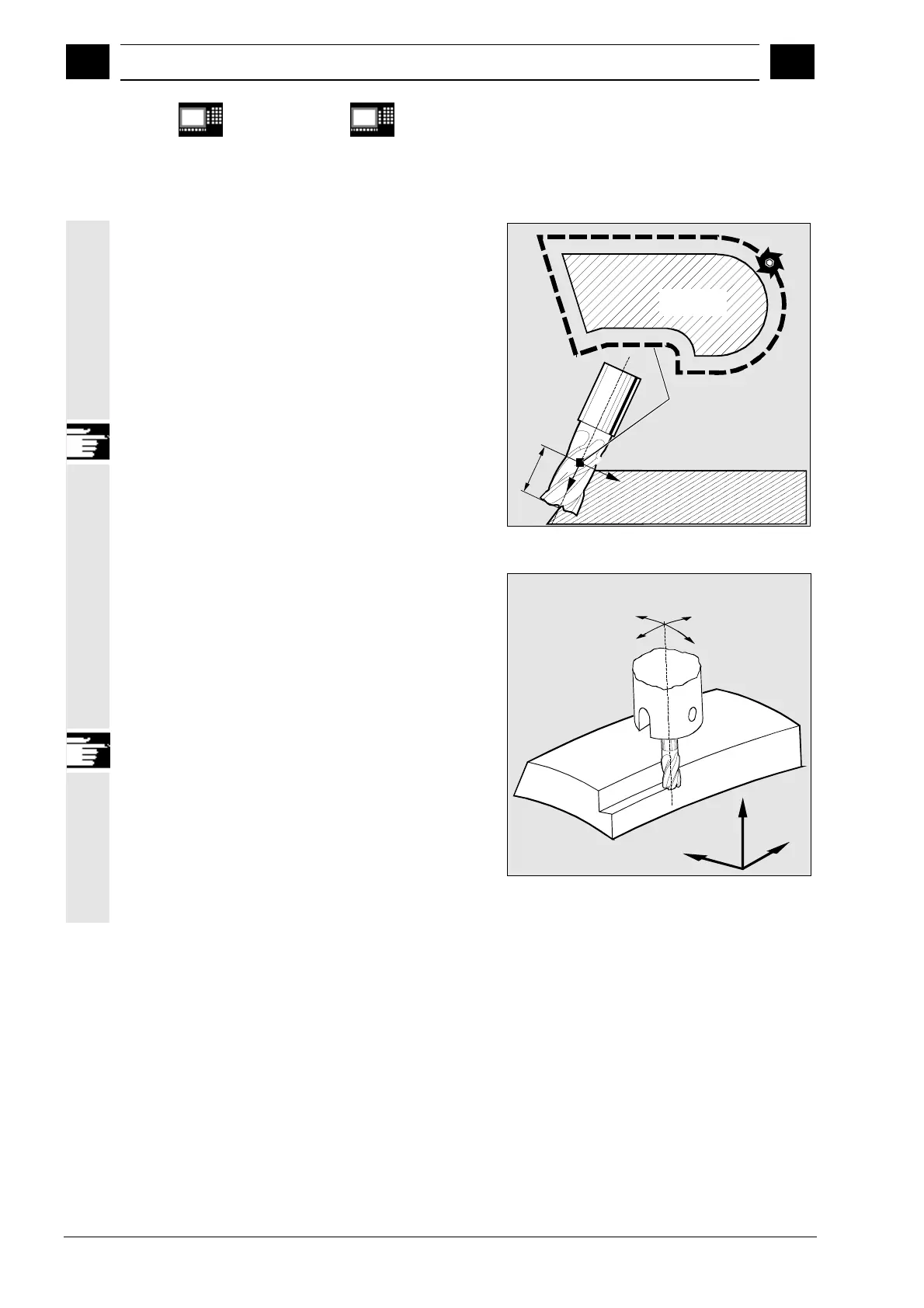
Difference between 2 1/2D and 3D tool radius
compensation
In 3D tool radius compensation tool orientation can
be changed.
2 1/2D tool radius compensation assumes the use of
a tool with constant orientation.
3D tool radius compensation is also called 5D tool
radius compensation, because in this case 5
degrees of freedom are available for the orientation
of the tool in space.
ISD
L
R
Path of tool center point
equidistant from contour
Workpiece
contour
Circumferential milling
The type of milling used here is implemented by
defining a path (guide line) and the corresponding
orientation. In this type of machining, the shape of
the tool on the path is not relevant. The only deciding
factor is the radius at the tool insertion point.
The 3D TRC function is limited to cylindrical tools.
A
B
Z
Y
X
Circumferential milling