4
Protection Zones 08.97
4.2 Activatin
/deactivatin
rotection zones: CPROT
NPROT
4
840D
NCU 571
840D
NCU 572
NCU 573
FM-NC 810D 840Di
Siemens AG 2000. All rights reserved
4-146
SINUMERIK 840D/840Di/810D/FM-NC Programming Guide Advanced (PGA)
−
04.00 Edition
Multiple activation of protection zones
A protection zone can be active simultaneously in
several channels (e.g. tailstock where there are two
opposite sides).
The protection zones are only monitored if all
geometry axes have been referenced. The following
rules apply:
•
The protection zone cannot be activated
simultaneously with different offsets in a single
channel.
•
Machine-oriented protection zones must have the
same orientation on both channels.
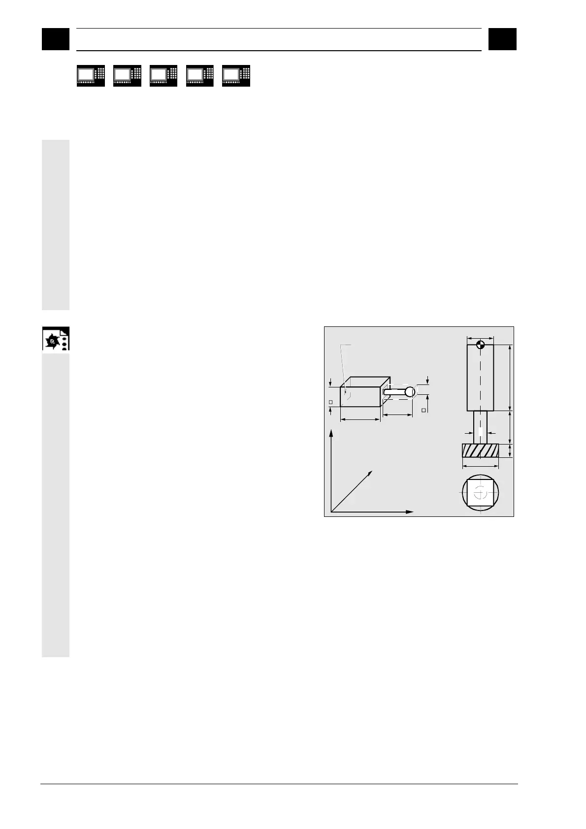
Programming example
Possible collision of a milling cutter with the
measuring probe is to be monitored on a milling
machine. The position of the measuring probe is to be
defined by an offset when the function is activated.
The following protection zones are defined for this:
•
A machine-specific and a workpiece-oriented
protection zone for both the measuring probe
holder (n-SB1) and the measuring probe itself
(n-SB2).
•
A channel-specific and a tool-oriented protection
zone for the milling cutter holder (c-SB1), the
cutter shank (c-SB2) and the milling cutter itself
(c-SB3).
The orientation of all protection zones is in the
Z direction.
The position of the reference point of the measuring
probe on activation of the function must be
X = –120, Y = 60 and Z = 80.
30
40
C-SB3
C-SB2
C-SB1
55
40
20
X
Z
Y
Reference point for
protection zone of
measuring probe
n-SB1
n-SB2
20
10
55
100
20

 Loading...


