7
Transformations 08.97
7.3 C
linder surface transformation: TRACYL
7
840D
NCU 571
840D
NCU 572
NCU 573
FM-NC
810D
840Di
Siemens AG 2000. All rights reserved
7-246
SINUMERIK 840D/840Di/810D/FM-NC Programming Guide Advanced (PGA)
−
04.00 Edition
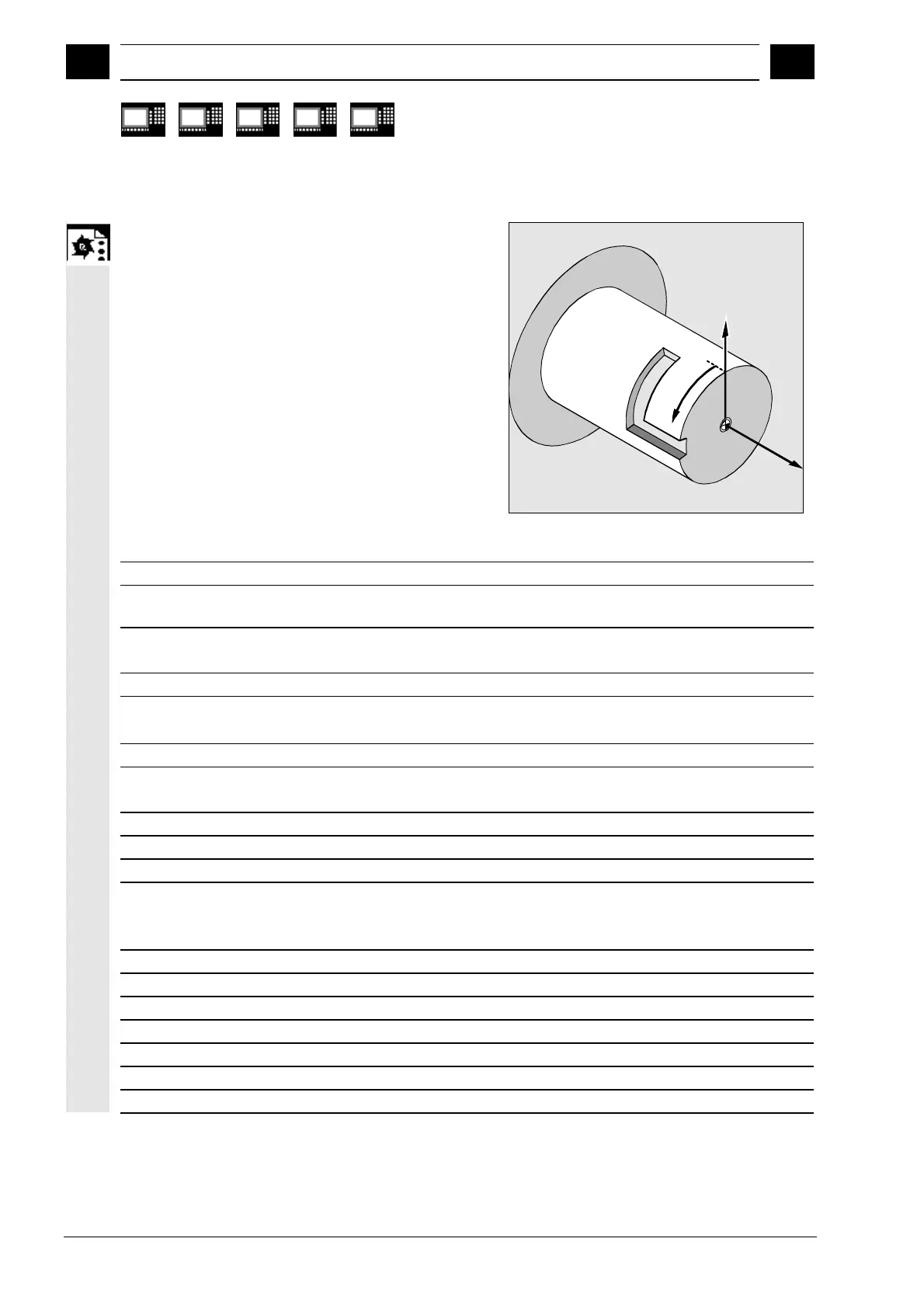
Programming example
X
Y
Z
N10 T1 D1 G54 G90 F5000 G94
Tool selection, clamping compensation
N20 SPOS=0
N30 G0 X25 Y0 Z105 CC=200
Approach reference point
N40 TRACYL (40)
Switch on cylinder surface curve
transformation
N50 G19
Select plane
Producing a hook-shaped groove:
N60 G1 X20
Infeed tool to base of groove
N70 OFFN=12
Set groove side distance 12 mm relative
to the groove center line
N80 G1 Z100 G42
Approach the right groove side
N90 G1 Z50
Groove section parallel to cylinder axis
N100 G1 Y10
Groove section parallel to circumference
N110 OFFN=4 G42
Approach left groove side; set groove
side distance 4 mm from to the groove
center line
N120 G1 Y70
Groove section parallel to circumference
N130 G1 Z100
Groove section parallel to cylinder axis
N140 G1 Z105 G40
Retract from the side of the groove
N150 G1 X25
Retract
N160 TRAFOOF
N170 G0 X25 Y0 Z105 CC=200
Approach reference point
N180 M30

 Loading...


