Overview screen
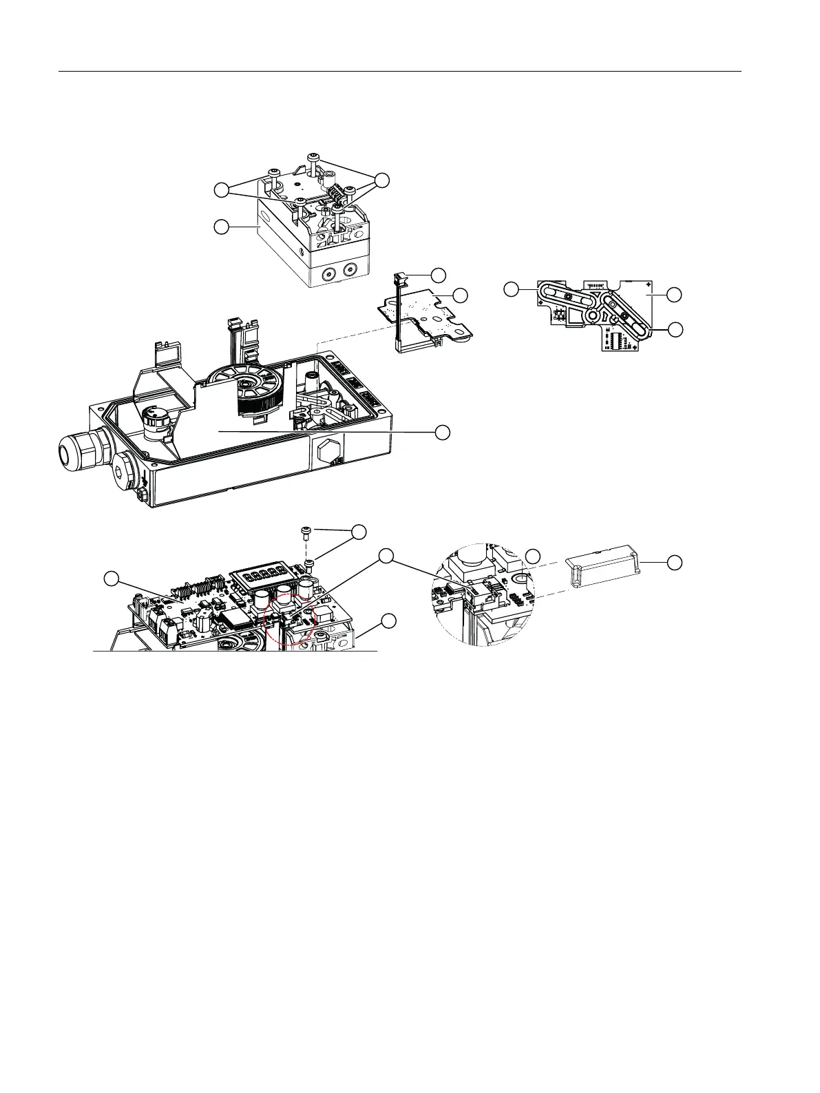
① Pneumatic block ⑥ Fixing screws basic electronics
② Mounting screws ⑦ Ribbon cable, covered with plastic cap ⑨
③ Pressure sensor module ⑧ Adapter
④ Cord seal ⑨ Plastic cap
⑤ Basic electronics
Figure 10-2 Pressure sensor, schematic diagram
Procedure
Removing
1. Switch off the supply pressure PZ and depressurize the actuator.
2. Open the positioner as described in section "Opening the standard and intrinsically safe
version (Page 52)".
3. Remove the plastic cap ⑨.
4. Remove the ribbon cable ⑦ and all other ribbon cables from the basic electronics ⑤.
Service and maintenance
10.6 Replace the pressure sensor module
SIPART PS2 with 4 to 20 mA/HART
204 Operating Instructions, 11/2019, A5E00074631-AE

 Loading...


