See also
'1.YFCT' type of actuator (Page 143)
5.2.4 Optional version M12 device plug
This section describes which terminal of the devices and option modules listed below is
connected with the respective pole of the M12 connector.
Note
Technical specifications
Observe the specifications for the electrical data in the certificate and/or in section "Technical
data (Page 239)".
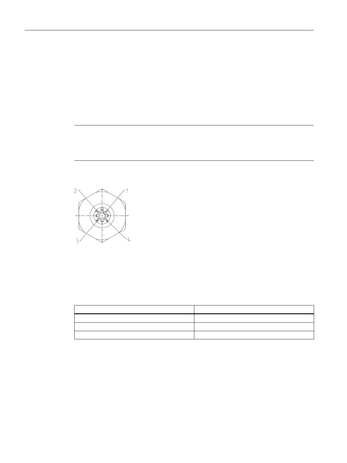
View of the mating side pole pattern
Pole desig‐
nation
Wire color of M12 ba‐
sic connector socket
1 Brown
4 Black
3 Blue
2 White
5.2.4.1 In the basic unit
You have a positioner 6DR50/1..-0.R.. or 6DR50/1..-0.S. In this version of the positioner, the
current input I
W
4 to 20 mA of the basic electronics is connected via the M12 connector.
Table 5-1 Assignment diagram
Current input terminal Pole designation
6 (+) 1 - Brown
Shield support of enclosure 4 - Black
7 and 8 (-) 3 - Blue
Connection
5.2 Electrical wiring
SIPART PS2 with 4 to 20 mA/HART
88 Operating Instructions, 11/2019, A5E00074631-AE

 Loading...


