Note
Leakage
Besides continuous air consumption, a leakage can cause the positioner to try to compensate
the position deviation. This will result in premature wear in the entire control device.
● Check offline for leakage using the "11.LEAK" diagnostic parameter.
● If there is leakage, check the pneumatic connections for leaks.
See also
Behavior in case of failure of the electrical auxiliary power and/or the supply pressure PZ
(Page 93)
Changing the operating mode (Page 98)
Diagnostic value '11.LEAK - Leakage test' (Page 217)
5.3.2 Pneumatic connection in non-flameproof enclosure
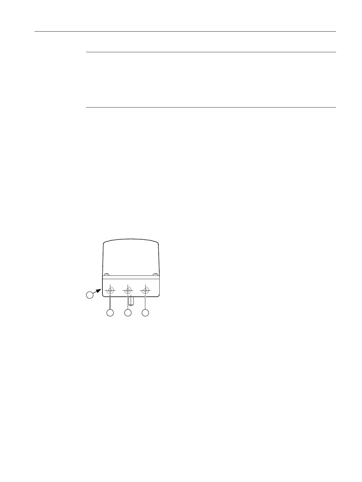
5.3.2.1 Structure of pneumatic connection
① Output: Actuating pressure Y2 *)
② Input: Supply pressure PZ
③ Output: Actuating pressure Y1
④ Exhaust air outlet with sound absorber, thread G¼
*) for double-acting actuators
Figure 5-12 Pneumatic connection, example
5.3.2.2 Integrated pneumatic connection
The following pneumatic connections are provided at the rear side of the basic device for the
integrated attachment for single-acting linear actuators:
● Actuating pressure Y1
● Exhaust air outlet
Connection
5.3 Pneumatic connection
SIPART PS2 with 4 to 20 mA/HART
Operating Instructions, 11/2019, A5E00074631-AE 91

 Loading...


