These connections are sealed with screws when the device is delivered.
The exhaust air outlet is corrosion-resistant for the blanketing of the pick-up room and the
spring chamber with dry instrument air.
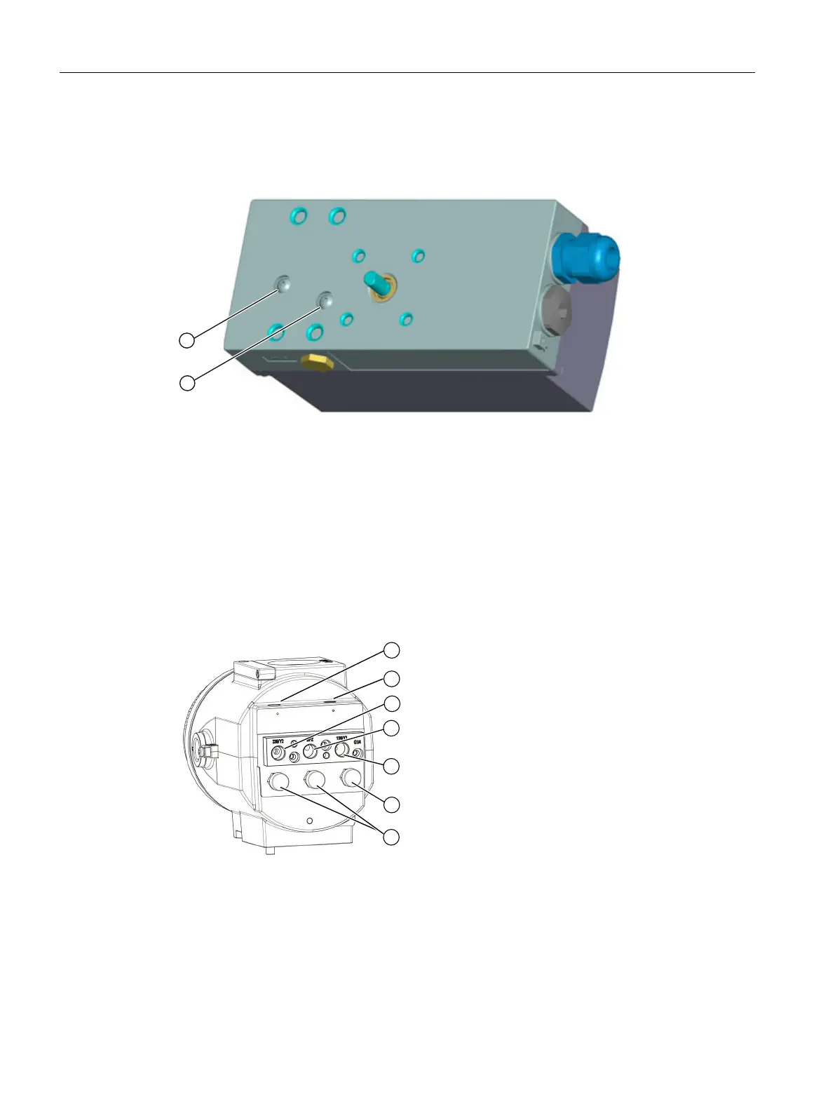
① Actuating pressure Y1
② Exhaust air outlet
Figure 5-13 Integrated pneumatic connection
5.3.3 Pneumatic connection in the flameproof enclosure
Structure
The pneumatic connections are provided on the right side of the positioner.
① Restrictor Y2
*)
⑤ Output: Actuating pressure Y1
② Restrictor Y1 ⑦ Enclosure ventilation (2x)
③ Output: Actuating pressure Y2
*)
⑥ Exhaust air outlet
④ Input: Supply pressure PZ
*) for double-acting actuators
Figure 5-14 Pneumatic connection in the flameproof enclosure
Connection
5.3 Pneumatic connection
SIPART PS2 with 4 to 20 mA/HART
92 Operating Instructions, 11/2019, A5E00074631-AE

 Loading...


