3.3 Device components
3.3.1 Overview of device components
::
r
r
P$
P$
%,1
r
r
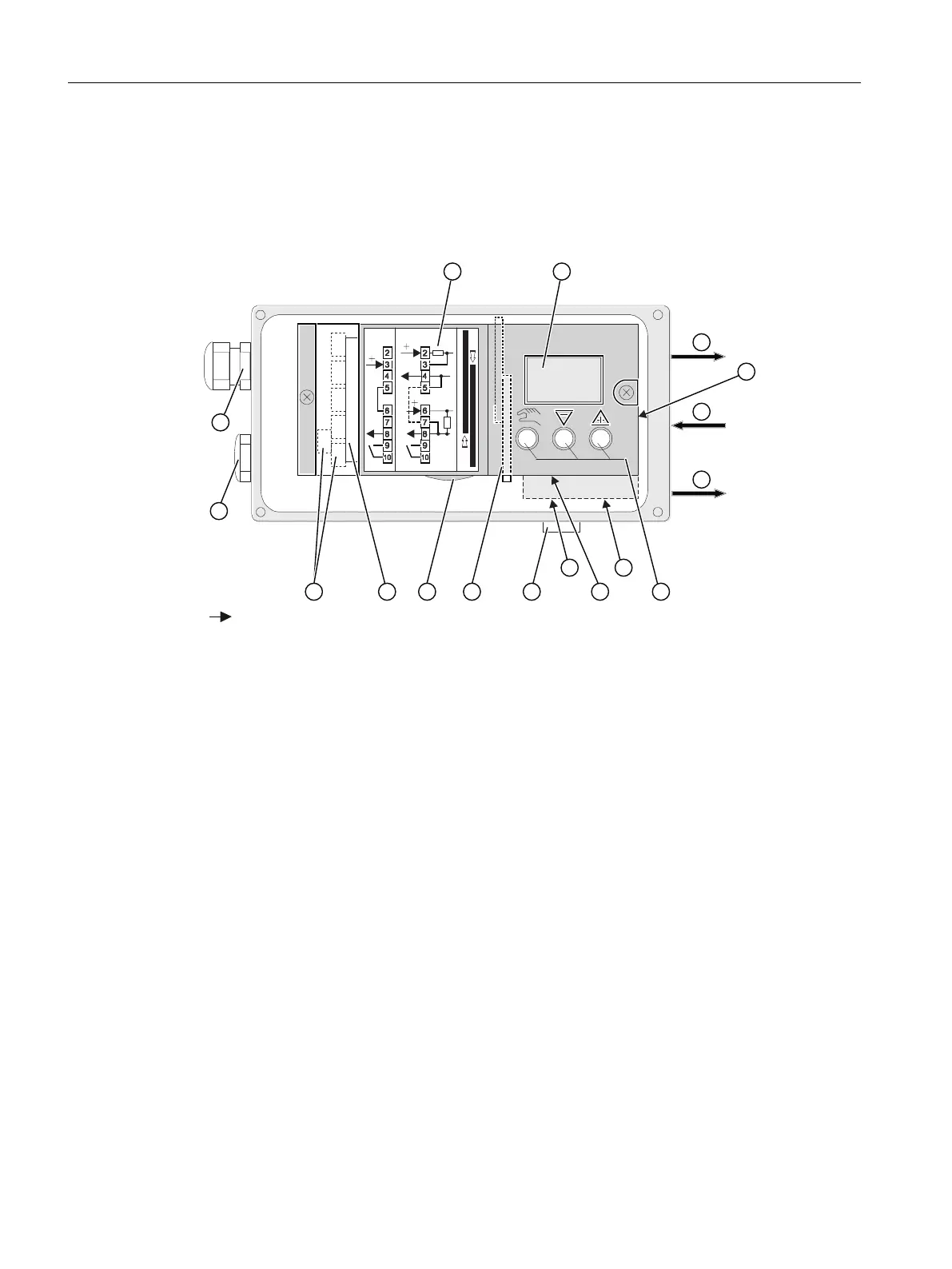
Arrowhead means: Turn the device to see the corresponding view
① Wiring diagram on module cover ⑩ Restrictor Y1 for double-acting actuators
② Display ⑪ Exhaust air outlet with a sound absorber
③ Output: Actuating pressure Y1 ⑫ Transmission ratio selector
2)
④ Input: Supply pressure PZ ⑬ Friction clutch adjustment wheel
⑤ Output: Actuating pressure Y2
1)
⑭ Basic electronics
⑥ Purging air selector ⑮ Connecting terminals of option modules
⑦ Buttons ⑯ Blanking plug
⑧ Restrictor Y2 for double-acting actuators
1)
⑰ Cable gland
⑨ Restrictor Y1 for single-acting actuators
1)
for double-acting actuators
2)
visible when the positioner is open
Figure 3-6 View of positioner with cover open
See also
Structure of pneumatic connection (Page 91)
Description
3.3 Device components
SIPART PS2 with 4 to 20 mA/HART
28 Operating Instructions, 11/2019, A5E00074631-AE

 Loading...


