Description
The dimensions of magnet and NCS can be found under Dimensional drawing of non-
contacting sensor (Page 285).
s
s
$
%&
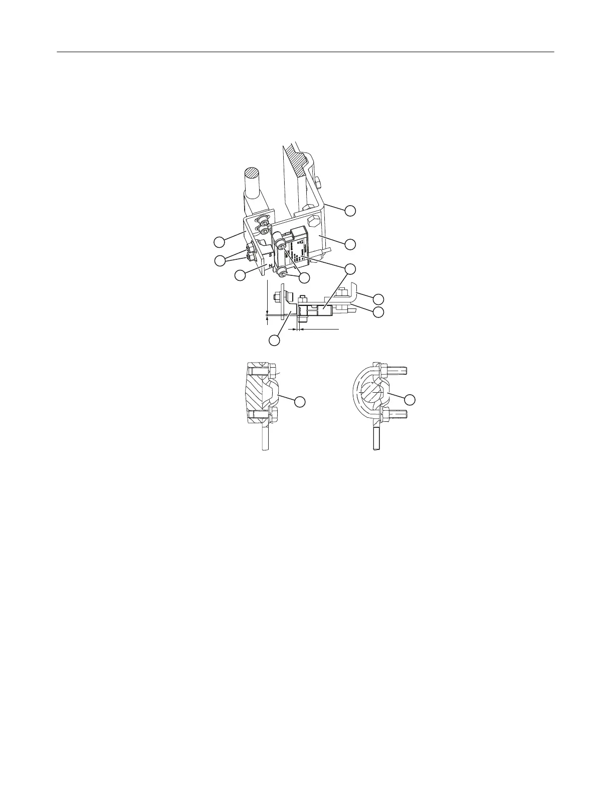
Dimensions in mm
A Mounting on a yoke with fin ③ Non Contacting Sensor (NCS)
B Mounting on a yoke with plane surface ④ Hex socket head screw M6x25
C Mounting on a yoke with columns ⑤ Magnet
① NAMUR mounting bracket IEC 60534 -
not included in the scope of delivery
⑥ Hex socket head screw M6x12
② Assembly panel for Non Contacting
Sensor (NCS) - individual solution; not
included in the scope of delivery
⑦ Mounting bracket for the magnet - individual
solution; not included in the scope of delivery
Figure B-5 Example of the assembly on a linear actuator with a stroke up to 14 mm (0.55 inch)
Procedure
1. Produce the mounting panel ② and mounting bracket ⑦ individually.
2. Align the sensor to the center of the stroke. Observe the dimensions specified in the figure.
External position detection
B.2 Non-Contacting Sensor
SIPART PS2 with 4 to 20 mA/HART
Operating Instructions, 11/2019, A5E00074631-AE 277

 Loading...


