Connecting
a
a
a
a
'51*$$
8
$X[
,
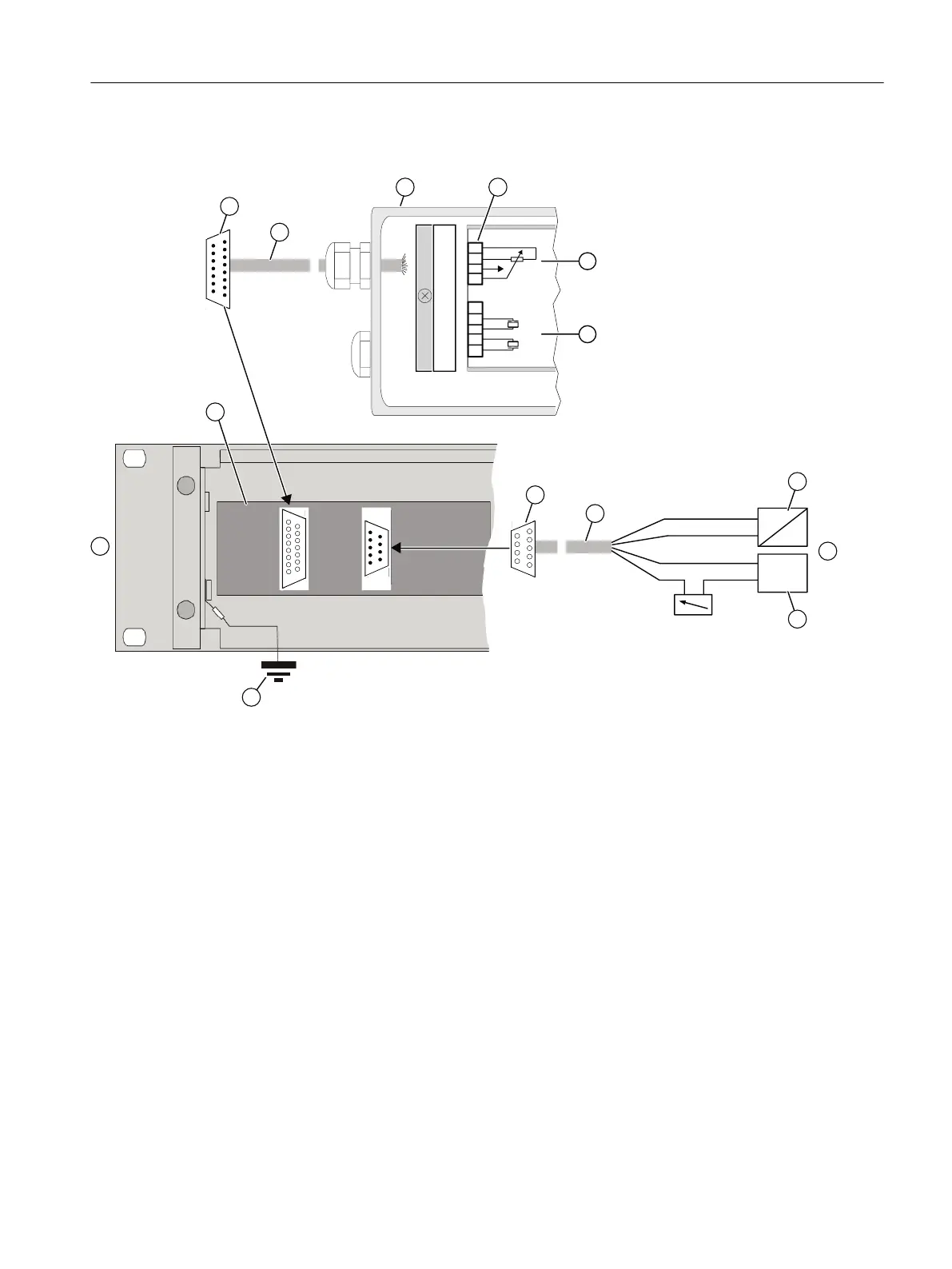
① D-SUB male connector 15-pin ⑧ Cable to control system
② Cable to the positioner 6DR5910 ⑨ Signal source
③ Positioner 6DR59.. ⑩ Control system
④ Connecting terminals, positioner ⑪ Auxiliary power supply U
Aux
⑤ Signal cables for potentiometer ⑫ Earth potential
⑥ Signal cables for pneumatic block ⑬ Control electronics in the 19" slide-in module
4 to 20 mA
⑦ D-SUB female connector 9-pin ⑭ Channel 1 of 3
Figure F-4 Connecting basic electronics to power supply
Procedure
Observe the safety instructions for connection in section Basic safety instructions (Page 75).
1. Strip 5 mm of the cable shield on the cable ②.
2. Open the positioner 6DR5910. Unscrew the four fixing screws of the enclosure cover.
3. Insert the prepared cable ② through the cable entry of the positioner.
4. Tighten the cable entry.
Positioner with remote control electronics
F.2 19" slide-in module
SIPART PS2 with 4 to 20 mA/HART
Operating Instructions, 11/2019, A5E00074631-AE 315

 Loading...


