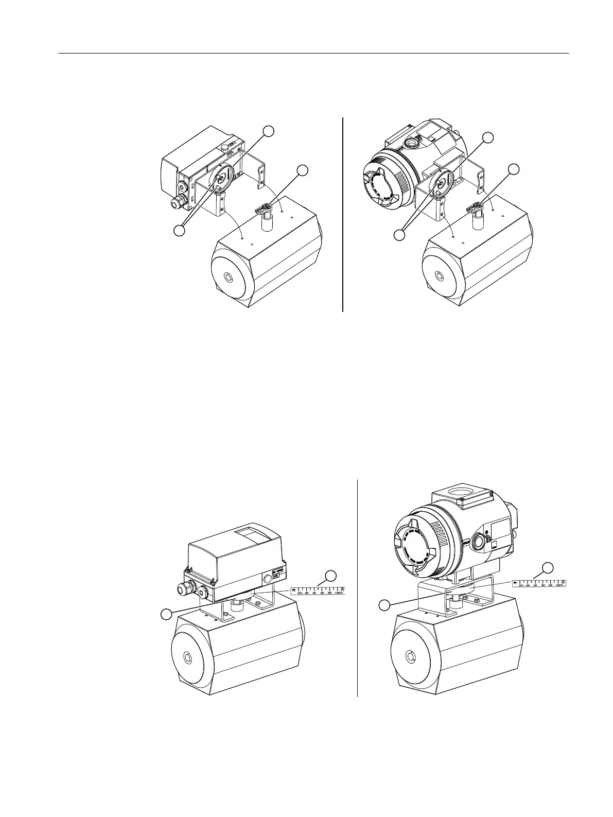
4. Place the positioner and the mount on the actuator carefully. One of the two pins ⑫ of the
coupling wheel ① must fit in the carrier ② when you do this.
Figure 4-9 Left: Orientation of mount; right: Orientation of mount, flameproof enclosure
5. When using the stainless steel coupling (article number TGX:16300-1556): Place the
positioner and the mount on the actuator carefully. Place the stainless steel coupling on the
stump of the actuator's positioner shaft.
6. Align the positioner with mount at the center of the actuator.
7. Fasten the positioner with mount.
8. Initialize the positioner.
9. After commissioning, drive the positioner to the end position.
10.Stick the scale ④ with the direction of rotation or the swivel range on the coupling wheel ①.
The stickers with scale are self-adhesive.
Figure 4-10 Left: Adhesive label with scale; right: Adhesive label with scale, flameproof enclosure
Installing/mounting
4.3 Mounting to part-turn actuator
SIPART PS2 with 4 to 20 mA/HART
Operating Instructions, 11/2019, A5E00074631-AE 47

 Loading...


