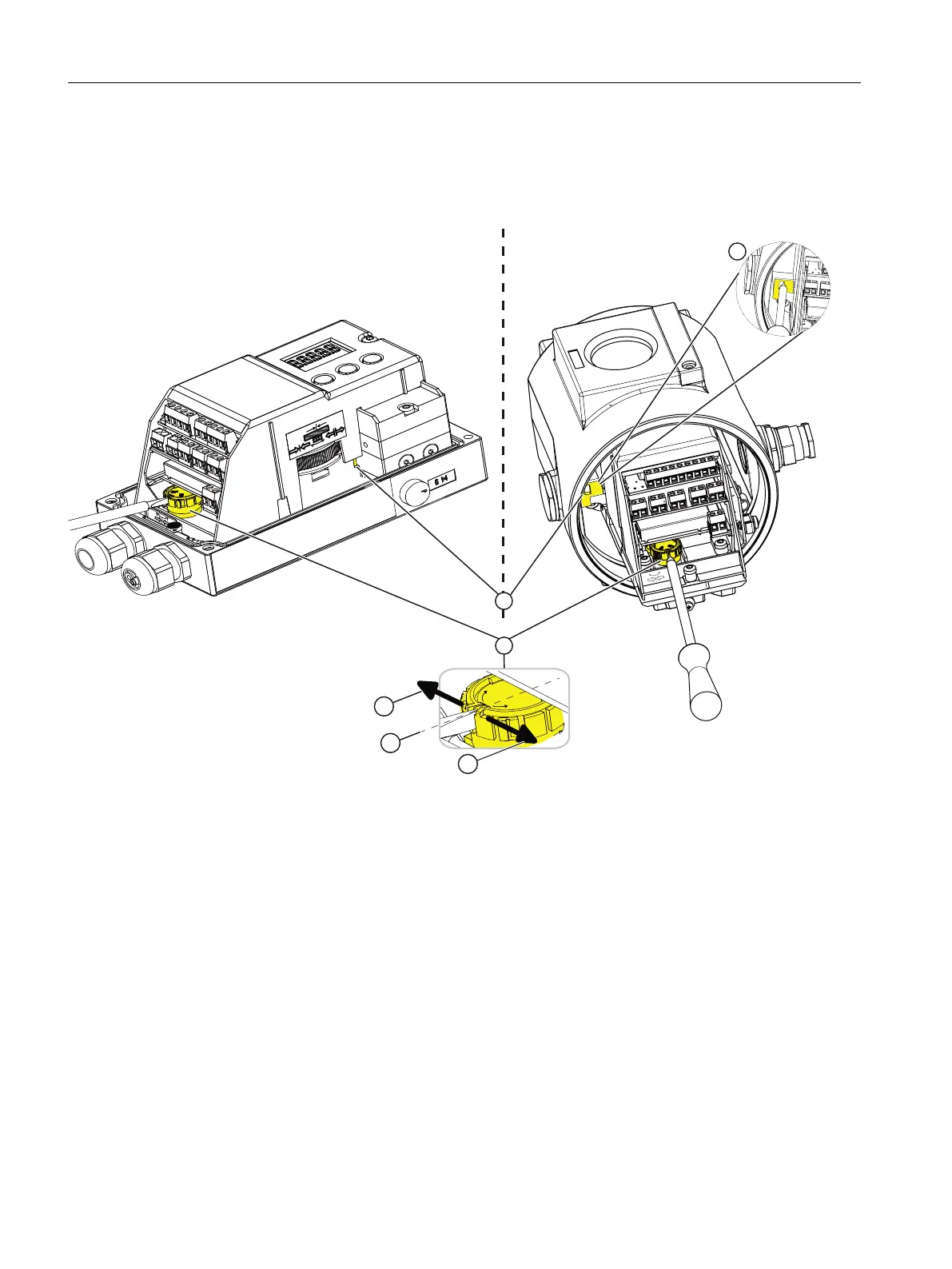
Procedure
On the right in the graphic the positioner is shown in the flameproof enclosure Ex d with open
cover. The procedure is the same for both enclosure versions.
r
r
r
([G
r
r
① Wheel for gear latch (yellow) ④ Locking transmission ratio to 90°
② Locking transmission ratio to 33° ⑤ Transmission ratio selector (yellow)
③ Neutral position
Figure 4-12 Locking the transmission ratio
1. Ensure that the wheel for the gear latch ① is in neutral position ③. The neutral position is
between 33° and 90°. The setting of the transmission ratio selector ⑤ can only be changed
effectively if the gear latch ① is in the neutral position ③.
2. Make sure the transmission ratio selector ⑤ is set to the same value as the gear latch ①,
either to 33° or to 90°.
3. Turn the wheel for the gear latch ① until the gear latch ① perceptibly locks. Use an approx.
4 mm wide standard screwdriver.
Turning right locks the transmission ratio to 33° ②. Turning left locks the transmission ratio
to 90° ④.
The transmission ratio ② is set and locked.
Installing/mounting
4.4 Setting and locking the transmission ratio
SIPART PS2 with 4 to 20 mA/HART
50 Operating Instructions, 11/2019, A5E00074631-AE

 Loading...


