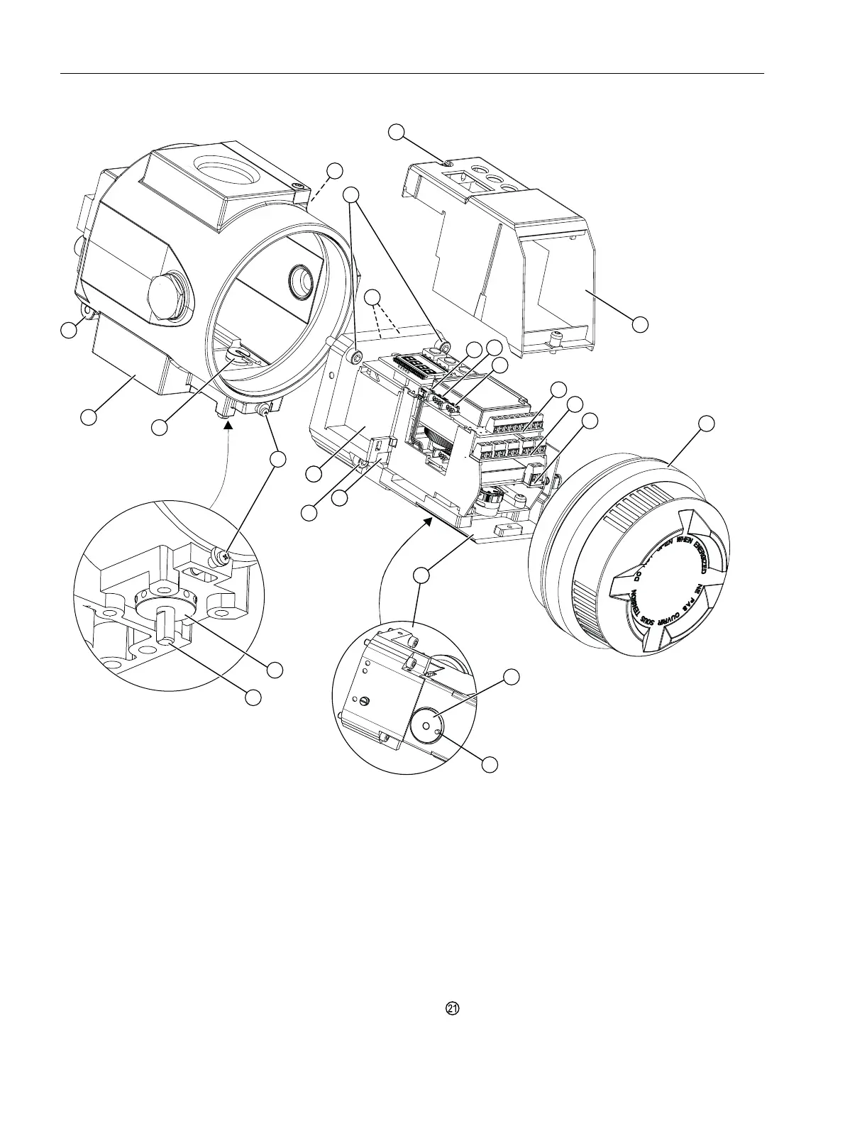
① Module cover ⑬ Pneumatic block
② Fixing screws module cover ⑭ Warning label on the side opposite the nameplate
③ Fixing screws basic electronics ⑮ Screw cap
④ Ribbon cable/connector for fitted potentiometer or Position
Transmitter
⑯ Feedback lever bracket with pin
⑤ Ribbon cable/connector for Digital I/O Module (DIO), In‐
ductive Limit Switches (ILS) or Mechanic Limit Switches
(MLS)
⑰ Pin (feedback lever bracket)
⑥ Ribbon cable/connector for Analog Output Module (AOM) ⑱ Adjustment wheel for external friction clutch
⑦ Basic electronics ⑲ Feedback shaft
⑧ Digital I/O Module (DIO) ⑳ Fixing screws adapter
⑨ Analog Output Module (AOM) Safety catch
Installing/mounting
4.5 Installing option modules
SIPART PS2 with 4 to 20 mA/HART
56 Operating Instructions, 11/2019, A5E00074631-AE

 Loading...


