Procedure
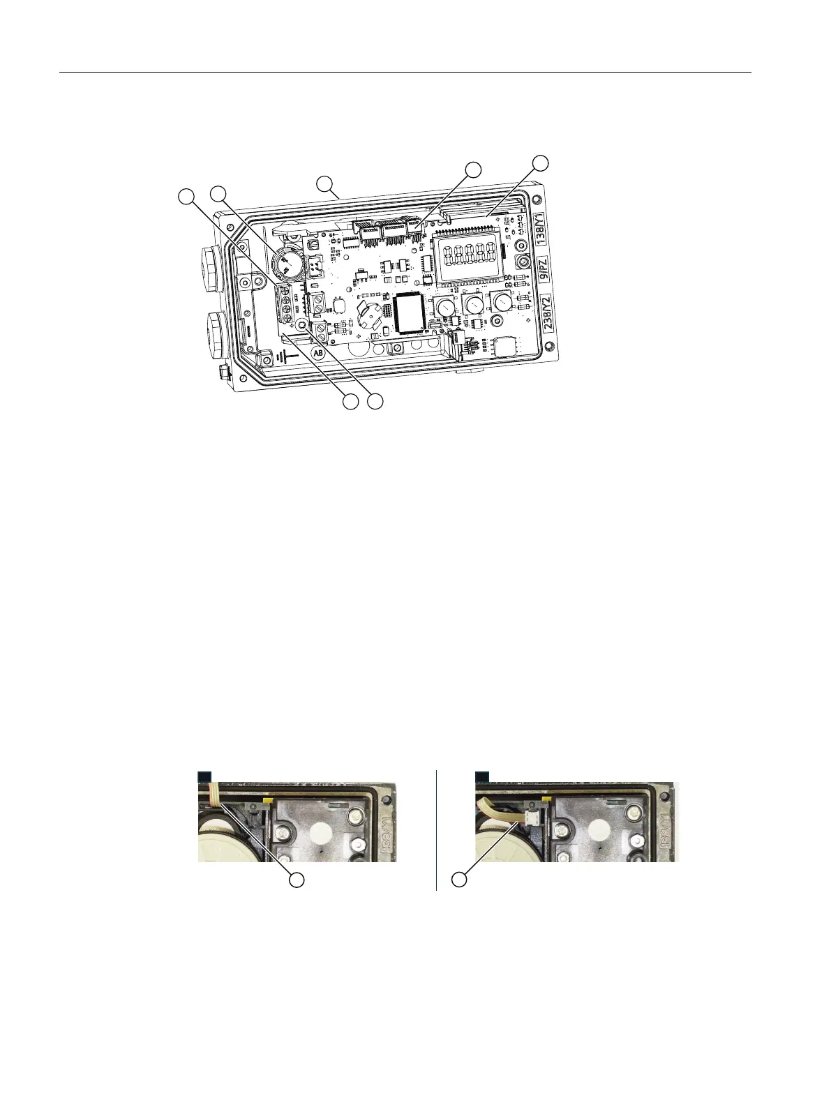
① Terminals of the Analog Input Module (AIM) ⑤ Basic electronics
② Yellow wheel for locking the position detection ⑥ Screw
③ Positioner ⑦ Analog Input Module (AIM)
6DR4004-6F/-8F
④ Ribbon cable connector of fitted potentiometer
or ribbon cable connector of Analog Input Mod‐
ule (AIM)
Figure 4-21 Installation of Analog Input Module (AIM)
1. Open the positioner as described in Opening the standard and intrinsically safe version
(Page 52).
2. Remove the ribbon cable from the basic electronics.
3. Loosen the two fixing screws of the basic electronics ⑤.
4. Remove the basic electronics.
5. Loosen the screw ⑥ in the connection area of the positioner.
6. Insert the connector of the ribbon cable (A) into the slot as shown below.
Note: There is no space for the ribbon cable (A) in earlier versions of the positioner. Here
you fasten the ribbon cable with the supplied cable tie at the container.
7. Secure the Analog Input Module (AIM) using the screw ⑥.
8. Place the basic electronics ⑤ onto the four holders of the adapter.
9. Screw in the two fixing screws of the basic electronics ⑤.
10.Tighten the screws.
Installing/mounting
4.5 Installing option modules
SIPART PS2 with 4 to 20 mA/HART
72 Operating Instructions, 11/2019, A5E00074631-AE

 Loading...


