Procedure
1. Loosen the screw ① on the transparent cover ②.
2. Pull the transparent cover ② up to the front end stop.
3. Tighten every cable in the corresponding terminal.
4. Slide the transparent cover ② up to the end stop of the basic electronics.
5. Tighten the screw ① of the transparent cover ②.
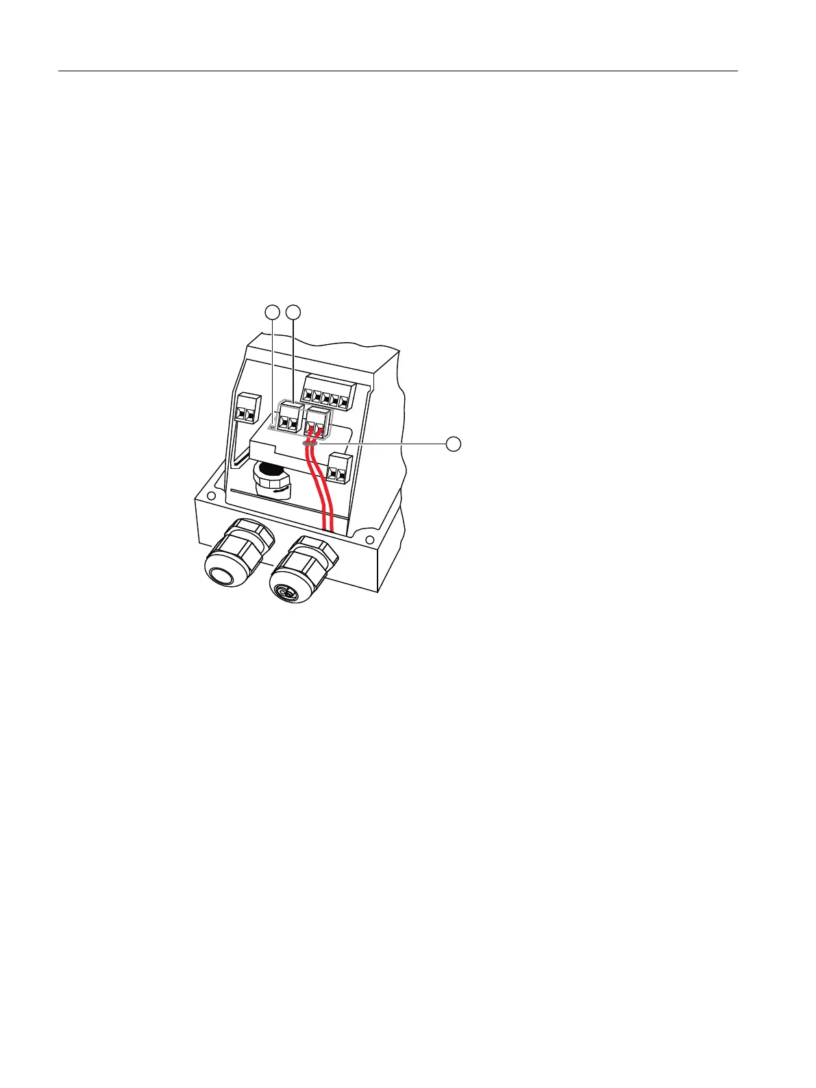
6. Connect the cables of each switch to the lug of the printed circuit board in pairs. Use the
provided cable ties ③ for this purpose.
① Screw
② Cover
③ Cable tie
Figure 5-11 Connecting the cables
Connection
5.2 Electrical wiring
SIPART PS2 with 4 to 20 mA/HART
86 Operating Instructions, 11/2019, A5E00074631-AE

 Loading...


