[lo-lokal-drahtbruch-110428, 1, en_US]
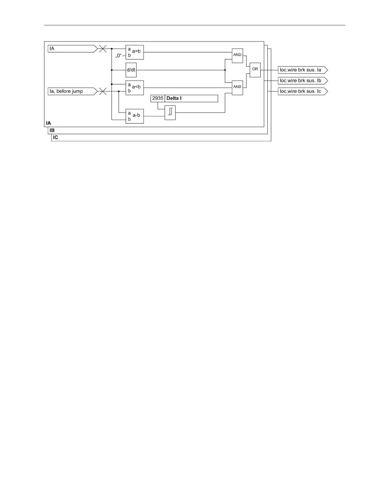
Figure 2-67 Generation of the local wire break
A wire break is signaled under the following conditions:
•
A suspected local wire break has been detected.
•
The logic for detecting the circuit-breaker position (see Section 2.16, Detection of the Circuit-Breaker
Position) does not signal an open circuit-breaker pole. Broken wire detection is not possible if the circuit
breaker is open. If the breaker position cannot be determined, a closed circuit breaker is assumed.
•
The ground current is measured on the additional current transformer Ι
4
. In this current channel and in all
voltage channels, no jump must have been detected. Jumps in these channels indicate a genuine power
system fault.
•
In the other current channels, there must have been no jump without wire break detection. Jumps in the
other current channels also suggest a power system fault, except if a suspected local wire break has been
detected for the affected phases.
•
The device at the other end of the protected object must not have signaled a jump. The jump information
is transferred together with the differential protection measurements, so that this information is available
simultaneously with the first run of the differential protection after the jump.
•
In the phase, none of the devices of the protected object may have measured a phase current of more
than 2 Ι
Nom
. A phase current of such a magnitude is a certain indicator of a power system fault.
When a wire break has been detected according to the above criteria, it is signaled via the protection data
interface to the device at the other end of the protected object and leads immediately to a wire break
message. The differential protection functions are blocked as well if this has been configured.
In the event of a local wire break, the device generates the indication “Wire break Ι
Lx
” (no. 290, 291, 292).
If a wire break is detected at the other end of the protected object, the indicatio “Wire break at the other end
Ι
Lx
” (no. 297, 298, 299).
If the broken wire monitoring is disabled, the message 295
Broken wire OFF
.
The broken wire monitoring is reset by the return of the phase current (Ι
Lx
> 0.2 Ι
Nom
) or by the binary input
message 3270
>RESET BW
. In 1-
1
/
2
circuit-breaker arrangements, the function can only be reset by the binary
input message because the current magnitude is no reliable criterion for a reset of the broken wire moni-
toring.
If the communication between the devices is disturbed, the device operates in emergency operation. The
differential protection is not active. The wire-break detection only works with the local available information.
Multipole wire break is not reported in emergency operation.
Note that electronic test devices do not simulate the correct behavior of broken wire so that pickup may occur.
Functions
2.14 Monitoring Functions
SIPROTEC 4, 7SD80, Manual 153
E50417-G1100-C474-A2, Edition 02.2018

 Loading...


