Connections of the Voltage Terminals
Fixing Elements
The fixing elements for the voltage transformer connection are part of the voltage terminal (housing side).
They have a stress-crack- and corrosion-resistant alloy. The head shape of the terminal screw allows for using a
flat screwdriver (4.0 mm x 0.8 mm / 0.16 in x 0.031 in) or a crosstip screwdriver (PZ1). PZ1 is recommended.
Cable Lugs and Wire Cross-sections
The connection mode available is the connection as single cable. As single cables, solid conductors as well as
stranded conductors with or without conductor sleeves can be used. We recommend using twin cable end
sleeves when connecting two single cables. We recommend the twin cable end sleeves of the series PN 966
144 from Tyco Electronics.
When connecting single cables, the following cross-sections are allowed:
Cable cross-sections:
AWG 20-14 (0.5 mm
2
to 2.0 mm
2
)
Connector sleeve with plastic collar L = 12 mm (0.47 in)
Stripping length:
(when used without conductor sleeve)
12 mm (0.47 in)
Only copper cables may be used.
With terminal points lying one below the other you may connect single conductors and jumpers (Order No.
C53207-A406-D194-1) together. Please make sure that neighboring jumpers are built in/connected alter-
nately.
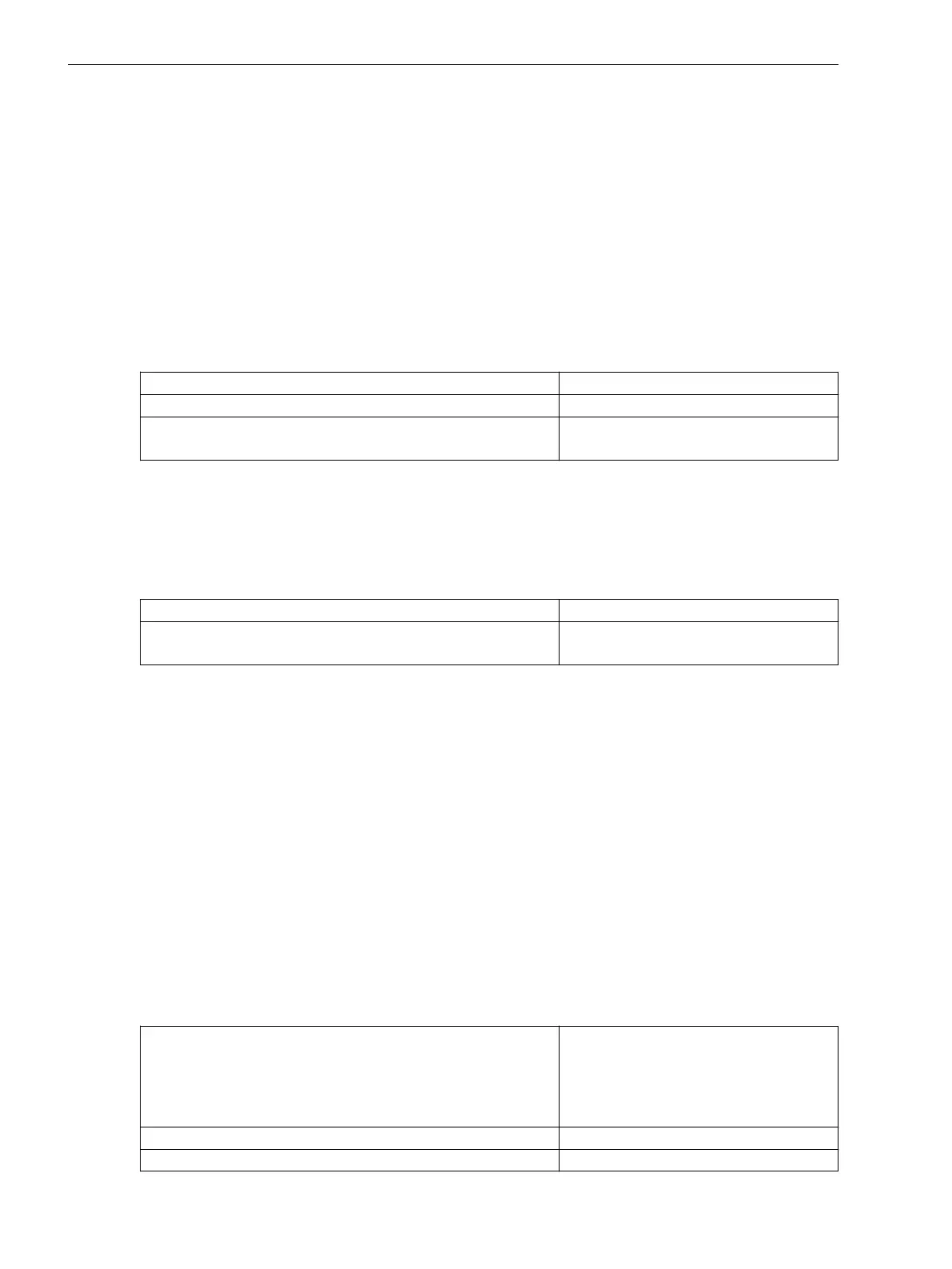
Mechanical Requirements
The fixing elements and the connected components are designed for the following mechanical requirements:
Permissible tightening torque at the terminal screw
1.0 Nm (8.85 lb.in)
Permissible traction per connected conductor 50 N based on IEC 60947-1
(VDE 660, Part 100)
Interface Modules
General
The 7SD80 relay is supplied with preconfigured interfaces according to the ordering version. You do not have
to make any adaptations to the hardware (e.g. plugging in jumpers) yourself, except for the installation or
replacement of communication modules.
The use of the interface modules RS232, RS485 and optical can be defined via the parameter 617 ServiProt
(CM). This parameter is only visible if the 11th digit of the ordering number was selected to be 1 for RS232, 2
for RS485 or 3 for optical.
Protection Interfaces
The 7SD80 features a CU protection interface and/or an optical fiber protection interface depending on the
ordering code.
When using the CU protection interface, you have to provide for an external transformer at the input of the
longdistance line cable, which provides protection against high induced voltages.
For example:
Regulating transformer (ordering code)
PCM transformer 6 kV contacting via
solder lugs (C53207-A406-D195-1)
or
PCM transformer 20 kV (screw terminals
for ring cable lug (7XR9516)
Frequency range 6 kHz bis 2000 kHz
Transformation ratio 1:1 (150 Ω:150 Ω)
3.1.2.3
3.1.2.4
Mounting and Commissioning
3.1 Mounting and Connections
214 SIPROTEC 4, 7SD80, Manual
E50417-G1100-C474-A2, Edition 02.2018

 Loading...


