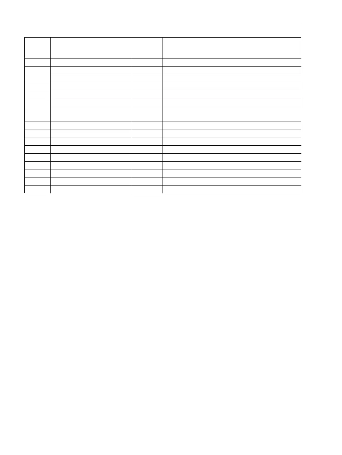
No. Information Type of
Informa-
tion
Comments
186 Error Board 4 OUT Error Board 4
187 Error Board 5 OUT Error Board 5
190 Error Board 0 OUT Error Board 0
191 Error Offset OUT Error: Offset
193 Alarm adjustm. OUT Alarm: Analog input adjustment invalid
194 Error neutralCT OUT Error: Neutral CT different from MLFB
320 Warn Mem. Data OUT Warn: Limit of Memory Data exceeded
321 Warn Mem. Para. OUT Warn: Limit of Memory Parameter exceeded
322 Warn Mem. Oper. OUT Warn: Limit of Memory Operation exceeded
323 Warn Mem. New OUT Warn: Limit of Memory New exceeded
2054 Emer. mode OUT Emergency mode
32200 PDITestFOon/OFF IntSP PDI Test Mode FO ON/OFF
32201 PDITestCuon/OFF IntSP PDI Test Mode Cu ON/OFF
32202 PDI Test Mode OUT PDI Test Mode
32203 PDI Test remote OUT PDI Test Mode remote
32224 PDI FO: AGING OUT PDI FO: aging (distance damping high)
32225 PDI Cu: AGING OUT PDI Cu: aging (distance damping high)
General Power System Data (Power System Data 1)
The device requires certain data regarding the network and substation so that it can adapt its functions to this
data depending on the application. The data required include for instance rated data of the substation and the
measuring transformers, polarity and connection of the measured quantities, if necessary features of the
circuit breakers, and others. Furthermore, there are several function parameters associated with several func-
tions rather than one specific protection, control or monitoring function. The Power System Data 1 can gener-
ally only be changed from a PC running DIGSI and are discussed in this section.
Setting Notes
Polarity of Current Transformers
In address 201 CT Starpoint the polarity of the current transformers must be entered, in other words, the
location of the CT starpoint (Figure 2-2). The setting defines the measuring direction of the device (current in
line direction is defined as positive at both line ends). The reversal of this parameter also reverses the polarity
of the ground current input Ι
N
.
2.1.3
2.1.3.1
Functions
2.1 General
36 SIPROTEC 4, 7SD80, Manual
E50417-G1100-C474-A2, Edition 02.2018

 Loading...


