Thermal Overload Protection 49
Setting Ranges
Factor k according to IEC 60255-8 0.10 to 4.00 Increments 0.01
Time Constant τ
th
1.0 min to 999.9 min Increments 0.1 min
Thermal Alarm Θ
Alarm
/Θ
Trip
50 % to 100 %
of the trip overtemperature
Increments 1 %
Current alarm element Ι
Alarm
for Ι
Nom
= 1 A
0.10 A to 4.00 A Increments 0.01 A
for Ι
Nom
= 5 A
0.50 A to 20.00 A
Calculation Method
Calculation method temperature rise Maximum temperature rise of 3 phases
Average of temperature rise of 3 phases
Temperature rise from maximum current
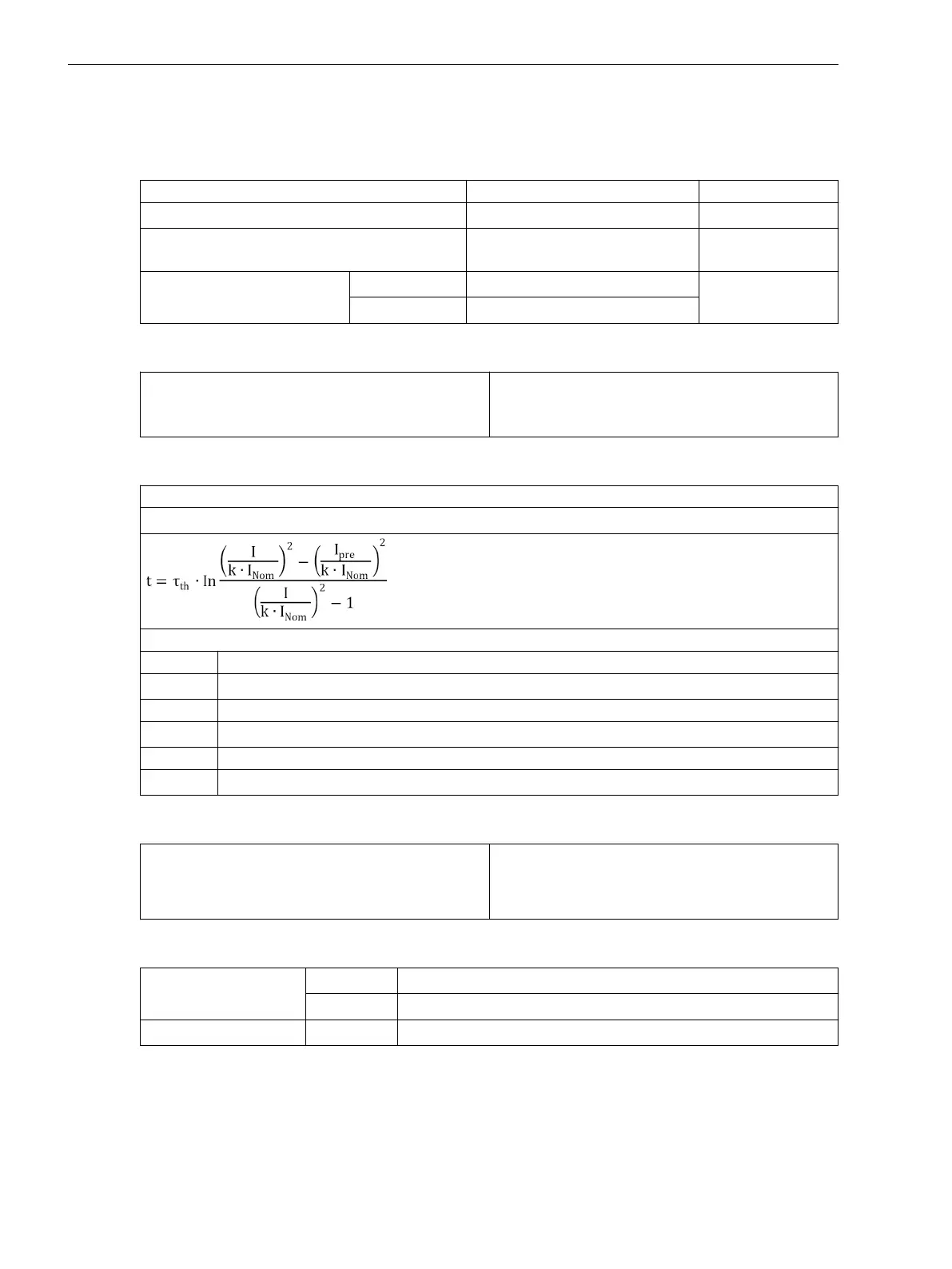
Trip Characteristic
Formula for primary values:
Trip Characteristic curve for Ι / (k ⋅ Ι
Nom
) ≤8
with
t Trip time in minutes
τ
th
Heating-up time constant
Ιn
Actual load current
Ι
pre
Preload current
k Setting factor per IEC 60255-8
Ι
Nom
Nominal current for the protected object
Drop-off to Pick-up Ratio
Θ/Θ
Trip
Θ/Θ
Alarm
Ι/Ι
Alarm
Drops out with Θ
Alarm
approx. 0.99
approx. 0.97
Tolerances
Referring to k ·
Ι
Nom
for Ι
N
= 1 A
3 % or 15 mA, 2 % class according to IEC 60255-8
for Ι
N
= 5 A
3 % or 75 mA, 2 % class according to IEC 60255-8
Referring to trip time
3 % or 1 s for Ι/(k ·Ι
Nom
) > 1.25, 3 % class according to IEC 60255-8
4.10
Technical Data
4.10 Thermal Overload Protection 49
276 SIPROTEC 4, 7SD80, Manual
E50417-G1100-C474-A2, Edition 02.2018

 Loading...


