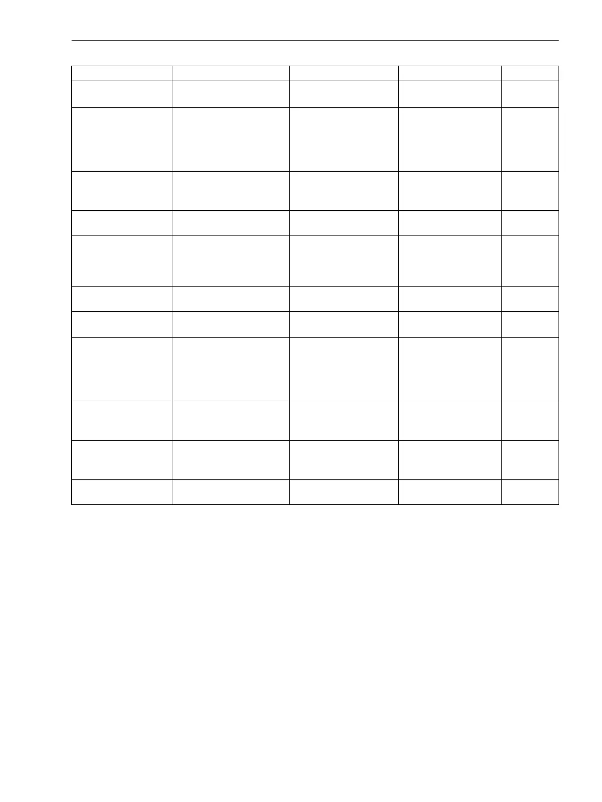
Monitoring Possible causes Fault response Indication (no.) Output
Adjustment values Internal (EEPROM or RAM) Indication:
Using default values
Alarm adjustm.
(193)
as routed
Modules Module does not comply
with order number (MLFB)
Indications:
Protection out of opera-
tion
“Störung BG1...5”
(183 ... 187)
und ggf.
Error A/D-conv.
.
(181)
DOK
2)
drops
out
Current sum Internal (measured value
acquisition)
Indication
Total blocking of the
differential protection
Failure Σi
(289)
as routed
Current symmetry External (power system or
current transformer)
Indication
Fail I balance
(163)
as routed
Broken wire External (power system or
current transformer)
Indication
Phase-selective blocking
of the differential protec-
tion
Broken Iwire L1
(290),
Broken Iwire
L2
(291),
Broken
Iwire L3
(292)
as routed
Voltage symmetry External (power system or
voltage transformer)
Indication
Fail V balance
(167)
as routed
Voltage phase
sequence
External (power system or
connection)
Indication
Fail Ph. Seq.
(171)
as routed
Voltage failure, 3-
phase“Fuse-Failure-
Monitor”
External (power system or
connection)
Indication
Undervoltage protection
blocked,
Frequency protection
blocked
VT FuseFail>10s
(169),
VT FuseFail
(170)
as routed
Voltage loss,
“Fuse-Failure-Monitor”
External (voltage trans-
formers)
Indication
Undervoltage protection
blocked,
VT FuseFail>10s
(169),
VT FuseFail
(170)
as routed
Voltage failure, 3-phase External (power system or
connection)
Indication
Undervoltage protection
blocked,
Fail V absent
(168)
as routed
Trip circuit supervision External (trip circuit or
control voltage)
Indication
74TC Trip cir.
(6865)
as routed
1)
Following three unsuccessful restarting attempts, the device is put out of operation
2)
DOK = “Device OK” = NC contact of the readiness relay = life contact
Setting Notes
General
The sensitivity of measured value monitoring can be modified. Default values which are sufficient in most
cases are preset. If especially high operational asymmetries of the currents and/or voltages are anticipated
during operation, or if it becomes apparent during operation that certain monitoring functions pick up sporad-
ically, then the setting should be less sensitive.
The measurement supervision can be switched ON or OFF in address 2901 MEASURE. SUPERV.
Symmetry Monitoring
Address 2902 BALANCE V-LIMIT determines the limit voltage (phase-to-phase), above which the voltage
symmetry monitor is effective. Address 2903 BAL. FACTOR V is the associated symmetry factor; that is, the
slope of the symmetry characteristic curve. The indication
Fail V balance
(no. 167) can be delayed at
address 2908 T BAL. V LIMIT. These settings can only be changed via DIGSI at Display Additional
Settings.
2.14.1.5
Functions
2.14 Monitoring Functions
SIPROTEC 4, 7SD80, Manual 159
E50417-G1100-C474-A2, Edition 02.2018

 Loading...


